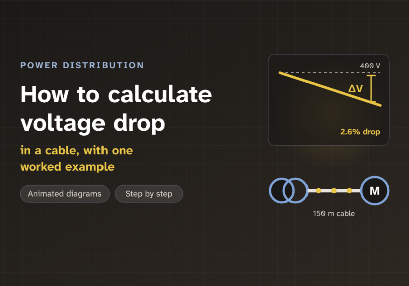
In this guide we follow the current along one real feeder, with animated diagrams, and work out how much voltage the load really gets.
Quick answer: Voltage drop is the voltage lost along a cable while current flows through it. It comes from the cable’s resistance and reactance. For a balanced three-phase circuit we use ΔV = √3 × I × L × (R cos φ + X sin φ). For a single-phase circuit we use 2 instead of √3, for the return wire. Then we divide by the nominal voltage and compare the result with a target, often 3% for one circuit and 5% for the whole path.
The problem: the load gets less than the source sends
Every cable carries current from a source to a load. The source is often a transformer or a distribution board. The load can be a motor, a lamp or a heater.
A real cable is not a perfect wire. It pushes back a little against the current. So some voltage is used up inside the cable itself. The voltage at the load end is lower than the voltage at the source end. This lost voltage is the voltage drop, written ΔV.
A small drop is normal. A large drop causes trouble. A motor on low voltage draws more current and runs hot. Lamps get dimmer. Electronic equipment can trip or reset. So how do we know, before we build, how much voltage the load will really get?
The figure shows the key point. The supply is the same in both panels. Only the cable length changes. The longer cable uses up more of the voltage on the way.
What causes the drop: resistance and reactance
A cable opposes current in two ways. The first is resistance, R. Resistance is the friction of the metal against the moving charges. It turns some energy into heat. A thicker conductor has less resistance. For copper at its working temperature, a good estimate is R ≈ 23.7 ÷ S ohms per kilometre, where S is the conductor size in mm².
The second is reactance, X. Reactance is opposition caused by the magnetic field around an AC conductor. The field builds up and collapses 50 or 60 times a second. Each time, it pushes back on the current. For low-voltage cables, X is small, about 0.08 Ω per kilometre. It matters most for large cables, above about 50 mm², where R is already low.
Together, R and X form the cable impedance, Z. Impedance is the total opposition to AC current. Both grow in step with the cable length.
Think of a long garden hose. The tap gives full pressure. But the water rubs on the hose wall all the way along. So the pressure at the nozzle is lower than at the tap. A longer or thinner hose loses more pressure. A cable loses voltage in the same way.
The core idea: only part of the impedance counts
We might expect the drop to be simply I × Z, current times impedance. But that is not quite right for AC. In AC, voltage and current are waves. They do not always peak at the same moment.
The power factor, cos φ, tells us how far apart they are. Here φ (the Greek letter phi) is the angle between voltage and current. A motor often has a power factor near 0.85, so the current lags the voltage by about 32°.
The drop across R points along the current. The drop across X points at right angles to the current. Only the part of these drops that lines up with the load voltage really changes its size. That part is I × (R cos φ + X sin φ). The phasor diagram below shows it. A phasor is an arrow whose length is the size of a wave and whose angle is its timing.
This gives the two standard formulas. Here I is the load current, L is the length in kilometres, and R and X are per kilometre:
Single-phase: ΔV = 2 × I × L × (R cos φ + X sin φ)
Three-phase: ΔV = √3 × I × L × (R cos φ + X sin φ)
The factor 2 is for the round trip. Current goes out on one wire and comes back on another. In a balanced three-phase circuit, there is no return current in the neutral. Instead we measure the drop between two phases, which brings in √3, about 1.732.
Think of a shadow at noon. A tall pole leans a little to one side. Its shadow on the ground is shorter than the pole. In the same way, only the "shadow" of the cable drop on the load voltage counts. The rest of the drop turns the voltage a little, but barely changes its size.
Do not use both factors at once. For a three-phase circuit, use √3 and the one-way length. Do not also double the length for a "return path". That counts the drop twice. The factor 2 belongs only to single-phase circuits.
Step by step: one feeder, four calculations
Let us size a real feeder. A 400 V three-phase supply feeds a motor control panel. The load current is 160 A at a power factor of 0.85. The cable is 150 m of 95 mm² copper. From R ≈ 23.7 ÷ 95, its resistance is about 0.249 Ω/km. Its reactance is about 0.08 Ω/km.
1Find R and X
Multiply the cable values per kilometre by the length. For 150 m, R is 0.0374 Ω and X is 0.012 Ω.
2Find sin φ
The power factor gives cos φ = 0.85. Its partner is sin φ = √(1 − 0.85²) = 0.527.
3Calculate ΔV
Add R cos φ and X sin φ. Then multiply by √3 and the current. The drop is about 10.6 V.
4Compare with the limit
Divide by the nominal voltage. 10.6 ÷ 400 is 2.6%, which is below the 3% target.
So the panel receives about 400 − 10.6 = 389.4 V. That is a drop of 2.6%. The X term added only 0.006 Ω out of 0.038 Ω, about one sixth. For a small cable it would add even less.
How much drop is allowed, and choosing the cable size
A drop only means something when we compare it with a target. Different standards give different targets, so we always check the one that applies to our project.
The IEC standard for building wiring, IEC 60364-5-52, gives a table in its Annex G. For an installation fed from the public low-voltage network, it suggests 3% for lighting and 5% for other uses. For an installation with its own private supply, such as its own transformer, it allows 6% and 8%. In North America, the NEC (National Electrical Code) gives advice in informational notes: 3% for one feeder or branch circuit, and 5% for the feeder and branch together.
Now the design rule. If the drop is too large, the main fix is a bigger conductor. Let us test three sizes for our 160 A, 150 m feeder. The calculation is the same each time. Only R changes.
With 50 mm², R is 0.474 Ω/km and the drop is about 18.5 V, or 4.6%. With 70 mm², R is 0.339 Ω/km and the drop is about 13.7 V, or 3.4%. With 95 mm², the drop is 10.6 V, or 2.6%. So 95 mm² is the smallest size that meets the 3% target. Note that the cable must also carry the current without overheating. That is a separate check, and the larger result wins.
The drop also grows in a straight line with length. Double the length and the drop doubles. Move the slider to see where our 95 mm² feeder stops meeting each target.
Assumes 400 V three-phase, 160 A, power factor 0.85, 95 mm² copper with R = 0.249 Ω/km and X = 0.08 Ω/km.
With these values, the feeder meets the 3% target up to about 170 m. Past about 285 m, it fails even the 5% total target. At that point we would choose a bigger cable, or run two cables in parallel.
Where voltage drop checks matter most
Engineers check voltage drop on almost every new circuit. But some cases need extra care.
Motor starting. A motor draws several times its full-load current while it starts, often at a low power factor near 0.35. The drop is much larger for a few seconds. The steady-state targets do not cover this moment. So we check it separately, to make sure the motor can still start and other loads do not dip too far.
Long runs. Street lighting, pumps at the far end of a site, car park chargers and farm buildings all sit far from the board. Here voltage drop, not heating, often decides the cable size.
Low voltage, high current. At 230 V and below, a few volts is a big percentage. Extra-low-voltage lighting and DC circuits, such as solar PV strings and battery links, are very sensitive. In DC there is no reactance, so we use only the resistance term.
Adding up the path. A load is often fed through a main feeder, a sub-board and a final circuit. We add the drops of every part. The total must still meet the whole-path target.
Key takeaways
- Voltage drop is the voltage used up inside a cable. It comes from resistance R and reactance X.
- Three-phase: ΔV = √3 × I × L × (R cos φ + X sin φ). Single-phase: use 2 instead of √3.
- Only the part of the cable drop that lines up with the load voltage counts. That is why cos φ and sin φ appear.
- For copper, R ≈ 23.7 ÷ S Ω/km. For low-voltage cables, X ≈ 0.08 Ω/km.
- Common targets are 3% for one circuit and 5% for the whole path. Check the standard for your project.
- The drop grows with current and length. A bigger conductor is the main fix.
Related guides on Electrical Blog:
ABCD Parameters: The Power Grid Perspective
Short Circuit Analysis Theory: Fault Current Calculations and X/R Ratios