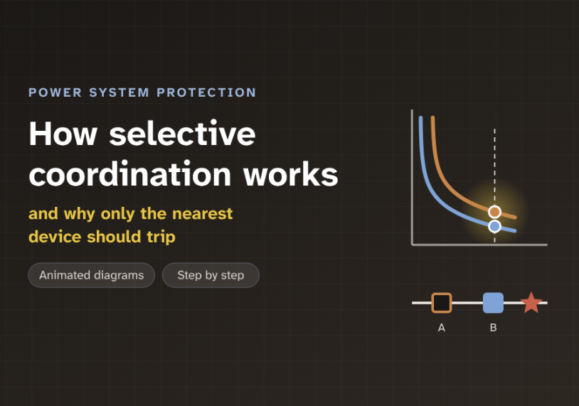
In this guide we follow one short circuit from a small branch back to the source, with animated diagrams, and see how the right breaker opens while the rest of the system stays on.
Quick answer: Selective coordination means that a fault is cleared only by the protective device nearest to it. Every device upstream, closer to the source, stays closed. The fault current flows through all of them, so the devices must take turns. Engineers do this with time-current curves: the downstream device gets a lower, faster curve, and each upstream device waits a little longer. The small extra wait is called the coordination time interval, often 0.2 to 0.4 seconds between relays.
The problem: one fault, many devices in its path
A power system is built like a tree. The source is the trunk. A main breaker sits at the top. Below it are feeder breakers. Below those are branch breakers, close to the loads.
Now imagine a short circuit on one small branch. A short circuit, or fault, is an unwanted low-resistance path. It makes a very large current flow. This fault current comes from the source. So it passes through the main, the feeder and the branch device, all at the same time.
Each of these devices sees the same high current. Each one could trip. So which one should open?
The answer is the one nearest the fault. Then only the faulted branch loses power. If the main breaker opens instead, the whole building goes dark for a problem on one circuit. The diagram below compares the two cases.
We call the good case selective coordination, or simply selectivity. "Selective" means the protection picks the right device. "Coordination" means the devices are set to work together in the right order.
A house has a water valve under each sink and one main valve at the street. If the kitchen tap leaks, we close the valve under the kitchen sink. The bathroom and the garden still have water. We close the street valve only if the kitchen valve fails. Selective coordination gives a power system the same habit.
The main parts: sense, decide, interrupt
Every protective device does three jobs. It senses the current. It decides when to act. Then it interrupts, which means it breaks the circuit.
In a medium-voltage feeder, three separate parts share these jobs. A current transformer (CT) senses. It is a ring around the conductor that makes a small copy of the current, for example 1 A for every 600 A. An overcurrent relay decides. It is a small electronic unit that compares the current with its settings. In drawings it has the device number 51, which means time-overcurrent. A circuit breaker interrupts. It is a switch that can open safely while a fault current flows.
The relay has two main settings. The pickup is the current at which the relay starts to act. Below the pickup, it does nothing. The time multiplier setting (TMS), also called the time dial, sets how long it waits. A bigger TMS means a slower relay.
In low-voltage systems, one part often does all three jobs. A fuse has a metal element that melts. A moulded-case circuit breaker has a built-in trip unit. The idea of coordination is the same for all of them.
The core idea: a race the nearest device must win
The key idea is inverse time. A small overcurrent gives a long wait. A large fault current gives a short wait. This is useful, because a small overload can be left for a while, but a short circuit must be cleared fast.
We draw this behaviour as a time-current curve, or TCC. The bottom axis is current. The side axis is trip time. Both axes use a log scale. On a log scale, each grid step is ten times the one before, so we can show 100 A and 10,000 A on one graph.
Now put the two curves on the same graph. Relay B is downstream, near the fault. Relay A is upstream, near the source. During a fault on B's circuit, both relays see the same current. So both start a race. For selectivity, relay B must always win this race.
That is the whole rule in one line: the downstream curve must stay below the upstream curve, and the two must not touch or cross. The vertical space between them, at the highest fault current, is the coordination time interval (CTI). It is the time margin that lets B finish its job before A runs out of patience.
Picture two guards at two gates, one behind the other. The inner guard is told: act after 3 seconds. The outer guard is told: act after 6 seconds. If the inner guard deals with the problem, the outer guard never needs to move. If the inner guard is asleep, the outer guard still steps in. That second guard is called backup protection.
A bigger rating upstream does not guarantee selectivity. A 400 A breaker above a 100 A breaker can still trip first. At high fault currents, both may trip on their fast instantaneous element, with no time delay. Only the time-current curves, checked at the maximum fault current, can prove coordination.
Step by step: one fault, four moments
Let us follow one fault on the circuit below breaker B. Each card shows one moment.
1Both start timing
A fault appears below breaker B. The same 5 kA flows through relay A and relay B. Both pass their pickup, so both start timing.
2The race
Each relay counts along its own curve. Relay B has the lower curve, so it reaches its trip time first, at 0.27 s.
3B opens
Relay B energises its trip coil. Breaker B opens within a few cycles. The arc goes out and the fault current stops.
4A resets
Relay A sees the current fall back to normal. Its timer resets before it ever reaches 0.58 s. Breaker A stays closed.
Step 4 is easy to miss. Relay A did start timing. But a time-overcurrent relay only trips if the current stays high for its full time. When the current stops, the relay resets. So the upstream breaker never moves.
The design rule: keep a time gap, with a worked example
How big must the gap be? The CTI has to cover three things. First, the opening time of breaker B, usually 3 to 5 cycles, or about 0.05 to 0.1 s. Second, errors in the relays and CTs, because no device is perfectly accurate. Third, a small safety margin.
Older electromechanical relays need about 0.3 to 0.4 s. Modern digital relays are more accurate, so 0.2 to 0.3 s is common. In this example we aim for 0.3 s.
Worked example. Take an 11 kV radial feeder. Relay B protects the outgoing circuit. It has a pickup of 400 A and a TMS of 0.10. Relay A sits upstream, with a pickup of 600 A. Both use the IEC standard inverse curve: trip time = TMS × 0.14 ÷ (M0.02 − 1). Here M is the fault current divided by the pickup. The highest fault current at relay B is 5 kA.
For relay B, M = 5000 ÷ 400 = 12.5. Its trip time is 0.10 × 0.14 ÷ (12.50.02 − 1) = 0.27 s. We want relay A to wait at least 0.3 s longer, so about 0.57 s.
For relay A, M = 5000 ÷ 600 = 8.33. With TMS = 1, the curve gives 3.23 s. So we need TMS = 0.57 ÷ 3.23 = 0.176. We round up to 0.18. Relay A then trips at 0.58 s, and the gap is 0.31 s. That meets the target.
There is one more check. The gap is not the same at every current. On this curve shape, it gets smaller as the current gets larger. So we always check at the maximum fault current. The slider below shows why. Move it and watch the gap.
Relay B: pickup 400 A, TMS 0.10. Relay A: pickup 600 A, TMS 0.18. IEC standard inverse curve. Target gap 0.3 s.
At 5 kA, the design point, the gap is 0.31 s. Above about 5.4 kA, it falls below 0.3 s. This matters when the utility strengthens its network, or a new transformer is added. The fault current rises, and the old settings may no longer be selective. So a coordination study must be repeated after such changes.
Where selective coordination is used
Good practice asks for selectivity almost everywhere. In industrial plants, it stops one motor fault from shutting a whole process line. On utility distribution feeders, engineers coordinate relays, reclosers and fuses in the same way. A recloser is a breaker that opens and then closes again on its own, to clear temporary faults.
For some systems, selectivity is the law. In the United States, the National Electrical Code (NEC) requires it for emergency systems (700.32), legally required standby systems (701.32) and critical operations power systems (708.54). It also applies to elevator circuits fed by more than one driving machine (620.62). So hospitals, high-rise buildings and data centres need a full coordination study.
Fuses make coordination simple. Manufacturers publish selectivity ratio tables. For many current-limiting fuses of the same type, an upstream fuse rated at least twice the downstream fuse (a 2:1 ratio) is selective at all fault levels in the table.
There is one trade-off. Each upstream device waits longer than the one below it. So a fault near the main bus is cleared more slowly. A slow clearing time means more arc-flash energy, the heat released by an electric arc. Engineers balance selectivity against safety. They use tools such as zone-selective interlocking, where devices talk to each other so the upstream one can trip fast when the fault is in its own zone.
Key takeaways
- Selective coordination means only the protective device nearest the fault opens. Everything upstream stays closed.
- Every protective device senses, decides and interrupts. With relays, a CT senses, the relay decides and the breaker interrupts.
- The time-current curve (TCC) shows trip time against current on log-log axes. The downstream curve must stay below the upstream curve and never cross it.
- The coordination time interval (CTI) covers breaker opening time, device errors and a safety margin: about 0.2 to 0.4 s between relays.
- Always check the gap at the maximum fault current. Repeat the study when the fault level changes.
- The NEC requires selectivity for emergency, legally required standby and critical operations power systems.
Related guides on Electrical Blog:
Short Circuit Analysis Theory: Complete Guide to Fault Current Calculations and X/R Ratios
A Friendly Guide to Installing REF Protection in Power Transformers