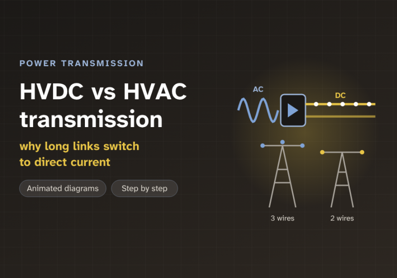
In this guide we send power down a long line, first as AC and then as DC, with animated diagrams, and find the distance where DC starts to win.
Quick answer: HVAC (high-voltage alternating current) is cheap to build and easy to connect, so it carries most of the grid. Over long distances, AC wastes capacity on charging current and struggles to keep both ends in step. HVDC (high-voltage direct current) avoids both problems, but it needs a costly converter station at each end. So AC is cheaper for short links and DC is cheaper for long ones. The crossover, called the break-even distance, is roughly 500 to 800 km for overhead lines and only about 50 to 100 km for cables.
The problem: AC gets tired over long distances
Almost all of the grid uses HVAC, high-voltage alternating current. Alternating current changes direction 50 or 60 times every second. AC has one big gift. A transformer, a simple device with two coils, can step its voltage up or down. That is why AC won the early grid.
But AC has a hidden cost. Every line and cable has capacitance, the ability to store charge between the conductor and its surroundings. With AC, this charge must be filled and emptied again every half cycle. The current that does this is called the charging current. It carries no useful power. But it still takes up space in the conductor.
In an overhead line the effect is small. In a cable it is large, because the conductor sits very close to the earthed metal sheath. So what happens when we make an AC cable longer and longer?
The charging current grows with every kilometre. At some length it fills the whole current rating of the cable. Then no real power can get through at all. The diagram below shows this for a 400 kV cable.
Long overhead AC lines have a second problem. The two ends must stay in step. The voltage angle between them grows with distance and with load. Past a limit, the two ends lose step and the link trips. This is the stability limit. Long AC lines need extra equipment, such as series capacitors and shunt reactors, to push this limit further.
DC has neither problem. Once the line is charged, a steady current flows. There is no charging current to carry and no angle to hold in step.
What is inside an HVDC link
The grids at both ends make and use AC. So an HVDC link is not just a DC wire. It is three parts in a row. A converter station turns AC into DC. A DC line or cable carries it. A second converter station turns it back into AC.
The sending station works as a rectifier, a converter that turns AC into DC. The receiving station works as an inverter, a converter that turns DC into AC. The same station can do either job, so power can flow both ways.
Each station holds a few main parts. The converter transformer sets the voltage and keeps DC out of the AC grid. The valves are stacks of power electronic switches. Classic stations use thyristors. This is called LCC, line-commutated converter. Newer stations use IGBTs, a faster transistor. This is called VSC, voltage-source converter. The smoothing reactor is a large coil that irons out the ripple in the DC current. The AC filters remove the unwanted harmonics, the extra frequencies the switching creates.
Most large overhead links are a bipole. A bipole has two conductors, one positive and one negative. The current goes out on one pole and comes back on the other. A three-phase AC line needs three conductors for a similar job. So the DC towers are lighter, and the strip of land under the line is narrower.
The core idea: a cable is a long capacitor
Why does the charging current grow so fast? Picture the cable as a long capacitor. The conductor is one plate. The earthed sheath is the other plate. The insulation between them is thin, so the capacitance is high. A typical 400 kV cable has about 0.2 µF (microfarads) per kilometre.
With AC at 50 Hz, this capacitor must charge and discharge 100 times every second. The charging current per kilometre is the phase voltage × 2π × frequency × capacitance. For our cable, that is 231 kV × 314 × 0.2 µF, or about 14.5 A for every kilometre. A large cable may be rated for about 1,500 A. So at about 100 km, the charging current alone fills it.
Imagine moving water through a long, stretchy hose. With AC, we push and pull the water 50 times a second. Most of our effort goes into swelling and shrinking the hose itself. Little water comes out of the far end. With DC, we fill the hose once. After that, every push moves water out of the far end.
A second piece of physics helps DC. Insulation must survive the peak voltage. An AC wave touches its peak only twice per cycle. Its useful value, the rms (root mean square) value, is only about 71% of the peak. A DC voltage stays flat. So the same insulation and conductor can carry more power on DC. This is one reason a DC bipole with two conductors can do the work of a three-conductor AC line.
DC also avoids the skin effect, the way AC current crowds near the surface of a conductor. DC current uses the whole cross-section, so the resistance is a little lower.
Step by step: from AC to DC and back
Let us follow the power through one HVDC link. Each card shows one stage.
1Set the voltage
The converter transformer takes AC from the grid. It sets the AC voltage the valves need. It also keeps DC out of the AC grid.
2Switch the valves
The valves are fast electronic switches. They connect each phase in turn, at the right moment. The output is DC with a small ripple.
3Smooth and send
The smoothing reactor, a large coil, irons out the ripple. Steady DC current then flows down the line, for hundreds or thousands of km.
4Turn it back
At the far end, the inverter switches the DC back into AC. It times the switching to the receiving grid, so the new AC is in step.
The power flow is set by the control system, not by the network. The operator picks a number, for example 1,500 MW, and the converters hold it. On an AC line, the power simply follows the physics of the network.
The design rule: the break-even distance
So DC is better over distance. But DC has a large fixed cost. Two converter stations cost a lot, and that cost is the same for a 100 km link or a 1,000 km link. The choice is a race between two kinds of cost.
An HVAC link has cheap ends. But each kilometre costs more. It needs three conductors, bigger towers, a wider path of land, and compensation equipment along the way. An HVDC link has costly ends. But each kilometre costs less.
A taxi has a small starting fee but a high price per kilometre. A long-distance train has a higher ticket price, but it costs little for each extra kilometre. For a trip across town, the taxi wins. For a trip across the country, the train wins. AC is the taxi. DC is the train.
Worked example. Take a 2,000 MW overhead link. We use round, illustrative numbers. The AC option has 150 million dollars (M$) of substations, plus 1.5 M$ per km of line. The DC option has 600 M$ of converter stations, plus 0.8 M$ per km.
At 300 km, AC costs 150 + 1.5 × 300 = 600 M$. DC costs 600 + 0.8 × 300 = 840 M$. AC wins. At 1,000 km, AC costs 1,650 M$ and DC costs 1,400 M$. Now DC wins. The break-even is where the costs are equal: (600 − 150) ÷ (1.5 − 0.8) ≈ 640 km. Real studies also add the cost of losses over 40 years, but the shape is the same.
Use the slider to move along the line and watch which option is cheaper.
Illustrative 2,000 MW overhead link. HVAC: 150 M$ of substations plus 1.5 M$ per km. HVDC: 600 M$ of converter stations plus 0.8 M$ per km. Real numbers vary a lot by country and route.
For cables, the AC cost per kilometre climbs much faster. Large compensation reactors are needed every few tens of kilometres, and that is very hard at sea. So for a sea crossing, the break-even falls to about 50 to 100 km. Above that, HVDC is often the only practical choice.
Many people think HVDC always has lower losses. It does not. Each converter station loses about 0.7% (LCC) to 1% (VSC) of the power. On a short link, those station losses can be more than the whole AC line loss. DC wins on losses only over long distances, where its lower line loss pays back the converter loss.
Three other tests can choose DC even below the break-even. Is the route a long cable? Are the two grids out of step, for example 50 Hz on one side and 60 Hz on the other? Do we need exact control of the power flow? If any answer is yes, HVDC is worth a close look.
Where HVDC and HVAC are used
HVAC runs the everyday grid. It carries power from power stations to cities, and between substations at ordinary distances. It is easy to tap at many points along the way. Almost every line we see on towers is AC.
HVDC takes the special jobs. Very long overhead lines move bulk power from far hydro, coal or solar sites to big cities. The Changji–Guquan line in China runs 3,293 km at ±1,100 kV and carries 12 GW. Long sea cables link countries. The North Sea Link joins Norway and the UK over 720 km. Offshore wind farms far from shore also use VSC HVDC cables.
Some HVDC links have no line at all. A back-to-back station puts the rectifier and the inverter in one building. It joins two grids that are not in step. Japan uses such stations to link its 50 Hz east and its 60 Hz west.
Key takeaways
- HVAC is cheap to build and easy to connect, so it carries most of the grid.
- Over long distances, AC loses capacity to charging current and is limited by stability. DC has neither problem.
- A cable is a long capacitor. A 400 kV AC cable draws about 14.5 A of charging current per km, so its rating is full at about 100 km.
- HVDC needs a rectifier and an inverter station. They are a large fixed cost and lose about 0.7–1% each.
- The break-even distance is roughly 500–800 km for overhead lines and about 50–100 km for cables.
- HVDC also links grids that are not in step and gives exact control of power flow.
Related guides on Electrical Blog: