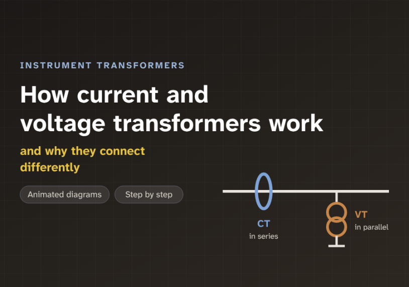
In this guide we follow one line signal from the high-voltage line to a relay, with animated diagrams, and see why a CT must never be opened and a VT must never be shorted.
Quick answer: A current transformer (CT) and a voltage transformer (VT) are instrument transformers. They shrink large line signals into small, standard ones for meters and relays. A CT is connected in series with the line. It gives a small current, usually 5 A or 1 A. A VT is connected in parallel across the line. It gives a small voltage, usually 110 V or 120 V. Because of this, a CT secondary must never be left open, and a VT secondary must never be short-circuited.
The problem: signals too big to measure
A transmission line can carry hundreds of amperes at a very high voltage. A 132 kV line, for example, may carry 800 A. A meter or a relay cannot be connected to that directly. A relay is the device that watches the line and tells the breaker to trip when there is a fault.
The relay needs a small copy of the line signal. The copy must be accurate, so the relay reads the real value. The copy must also be isolated from the line, so people and equipment stay safe. So how can a relay measure 800 A and 132 kV without touching them?
We use an instrument transformer. This is a transformer built to measure, not to carry power. It takes the large value on its primary side and gives a small, standard value on its secondary side. There are two types. The current transformer (CT) copies current. The voltage transformer (VT) copies voltage. A VT is also called a potential transformer (PT).
What is inside a CT and a VT
Both devices are transformers. Each has a magnetic core, made of steel, and two windings. A winding is a coil of wire. The primary winding is on the line side. The secondary winding is on the measuring side. But the two devices use their windings in different ways.
In a CT, the primary is the line conductor itself. It passes once through the core, so it is only one turn. The secondary has many fine turns wound around the core. A typical CT is marked 800/5. This means 800 A in the primary gives 5 A in the secondary.
In a VT, the primary has many turns and connects across the line. The secondary has fewer turns. A typical VT is marked 132 kV/110 V. This means 132 kV on the line gives 110 V in the secondary. It is the same idea as a power transformer, but built for accuracy instead of power.
Think of a water pipe. A CT is like a flow meter placed inside the pipe. All the water must pass through it. A VT is like a pressure gauge on a thin side tap. It only feels the pressure and takes almost no water.
The core idea: series versus parallel
A CT is a series device. The line current flows through it. This current is set by the load, not by the CT. The CT cannot change it.
A VT is a parallel device. It sits across the line. The line voltage is set by the grid, not by the VT. The VT cannot change it.
This one difference explains the two safety rules. Let us start with the CT.
The primary current makes magnetic flux in the core. Flux is the magnetic field that passes through the core. The secondary current makes flux in the opposite direction. The two nearly cancel. We say the ampere-turns balance. Ampere-turns means current multiplied by the number of turns. For an 800/5 CT, the primary has 1 turn and the secondary has 160 turns. So 800 A × 1 turn ≈ 5 A × 160 turns.
Now open the secondary. The secondary current stops, so nothing opposes the primary. The full primary ampere-turns now push flux into the core. The core saturates, which means it cannot carry any more flux. The figure below shows this curve.
Voltage is made by the rate of change of flux. In saturation, the flux changes very little for most of each cycle. Then it flips very fast near each zero crossing. These fast flips make tall, narrow voltage spikes. They can reach several kilovolts across the open terminals. This can hurt a person and break the insulation.
A CT is like a pump that insists on pushing a fixed flow of water. If the pipe is open, the water just flows. If we close the valve at the end, the pump still pushes. The pressure shoots up until something bursts. An open CT secondary is that closed valve.
Now the VT. It acts like a small voltage source. Its secondary feeds high-impedance meters, so only a tiny current flows. Impedance is the total opposition to alternating current. If we short the secondary, nothing limits the current except the winding itself. The current becomes very large and the VT overheats. So VT secondaries are protected with fuses or small breakers.
Some people think a spare CT with nothing connected is "off", so it is safe to leave open. It is not. A CT is live whenever the line carries current. If a CT is not used, its secondary terminals must be shorted together. Only a VT may be left open.
Step by step: one CT, four moments
Let us follow the current through one CT. Each card shows one moment.
1Line current flows
The line current passes through the core window. This is the one-turn primary.
2Flux builds in the core
The primary current makes magnetic flux. The flux circles around the steel core.
3Secondary current flows
The flux induces a small current in the many-turn secondary. For an 800/5 CT, it is 5 A at full load.
4The relay reads it
The relay reads 5 A. It multiplies by the ratio, 160, and knows the line carries 800 A.
A VT follows the same four moments, with voltage instead of current. The line voltage appears across the many-turn primary. It makes flux in the core. The flux induces a smaller voltage in the secondary. The relay reads about 110 V and multiplies by the ratio to find the line voltage.
Choosing ratio, class and burden
Three numbers decide whether an instrument transformer does its job. The first is the ratio. The second is the accuracy class. The third is the burden.
The burden is the load on the secondary. It is the total of the relays, meters and wires connected to it. We state it in volt-amperes (VA). A CT is rated for a maximum burden, for example 15 VA. If the real burden is higher, the CT loses accuracy and saturates sooner.
The accuracy class tells us how close the copy is. A metering class such as 0.2 or 0.5 means the ratio error stays within 0.2 % or 0.5 % at rated conditions. A protection class such as 5P20 means two things. The composite error stays within 5 %. This holds up to 20 times the rated current.
Now a worked example. A 132 kV line carries at most 650 A. We choose an 800/5 CT, ratio 160. At full load the relay sees 650 ÷ 160 ≈ 4.1 A. A fault of 20 kA gives 20,000 ÷ 160 = 125 A, which is 25 times the rated 5 A. But a 5P20 CT is only accurate to 20 × 5 = 100 A, which is 16 kA on the primary. So this CT may saturate in the fault, exactly when the relay needs it most. A 1600/5 CT (ratio 320) gives 62.5 A, or 12.5 times rated. That is inside the limit.
For the VT, a 132 kV system uses a ratio of (132/√3) kV to (110/√3) V. This is 76.2 kV per phase to 63.5 V. The ratio is 1200. A relay reading 63.5 V knows the phase voltage is 63.5 × 1200 = 76.2 kV.
The wires add to the burden. Let us see how much. The graph shows a CT rated 15 VA with a 0.5 VA relay. The cable is 2.5 mm² copper, which has about 7.41 Ω per km.
Assumes 2.5 mm² copper at 7.41 Ω/km, out-and-back wire, relay burden 0.5 VA, CT rated 15 VA. Burden = I² × R.
With these values, the 5 A CT stays within its 15 VA rating up to about 39 metres of cable. The 1 A CT stays within rating for almost a kilometre. This is why long cable runs in big substations often use 1 A secondaries. The same wire carries one fifth of the current, so its burden is 25 times smaller.
Where instrument transformers are used
They sit in almost every substation. Protection uses them most. Overcurrent, differential and distance relays all need a CT. Distance relays and synchronising checks also need a VT. Without them, the relay cannot see the fault.
Metering uses them for billing. Here the accuracy class matters most, because small errors become money. Control and monitoring systems use them too, to show current and voltage in the control room.
At 132 kV and above, a plain VT becomes large and costly. So we often use a capacitor voltage transformer (CVT). A CVT uses a stack of capacitors as a voltage divider, then a small VT. It gives the same kind of secondary signal at a lower cost.
Key takeaways
- CTs and VTs are instrument transformers. They give relays and meters a small, isolated, accurate copy of the line signal.
- A CT is in series and gives 5 A or 1 A. A VT is in parallel and gives about 110 V.
- A CT needs its secondary closed. If it is opened, the core saturates and kilovolts appear. Short unused CT terminals.
- A VT needs its secondary open, protected by a fuse. If it is shorted, the current is very large and the VT burns out.
- Ratio, accuracy class (such as 0.2 or 5P20) and burden decide how well the copy matches the line.
- Long cables add burden. A 1 A secondary keeps that burden much smaller than a 5 A one.
Related guides on Electrical Blog:
A Friendly Guide to Installing REF Protection in Power Transformers
Short Circuit Analysis Theory: Fault Current Calculations and X/R Ratios