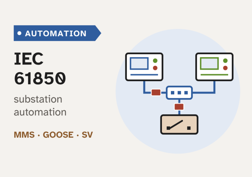
In this guide we learn how IEC 61850 lets protection relays, controllers and SCADA from different makers share one network and one data model, with clear diagrams of every part.
Quick answer: IEC 61850 is the international standard for communication in substation automation. It gives every device the same data model, so equipment from different makers understands each other. It defines three main services: MMS for monitoring and control, GOOSE for fast trip and interlock messages, and sampled values for streaming measurements. SCL configuration files describe the whole system. Ethernet networks then replace most of the copper wiring between devices.
Why IEC 61850 exists
A substation is full of intelligent electronic devices, or IEDs. An IED is a microprocessor-based device that protects, controls or measures part of the plant. Protection relays, bay controllers and meters are all IEDs.
For many years, each maker used its own protocol. A relay from one company could not easily talk to a controller from another. So utilities either bought everything from one vendor, or they added protocol converters and custom work.
Between the devices, most signals ran on copper. A trip, an alarm or an interlock each needed its own pair of wires. A large substation could have thousands of these wires. Each one had to be designed, drawn, installed and tested. And a broken wire often stayed hidden until the day it was needed.
So how can a relay from one maker trip a breaker controller from another maker, with no copper wire between them? This is the problem IEC 61850 solves. The figure below shows the change.
IEC 61850 is not one protocol. It is a family of standards, published by the International Electrotechnical Commission (IEC). Together they define three things:
- A data model. Every function and every value has a standard name, the same for every maker.
- Communication services. These are the ways devices exchange that data: MMS, GOOSE and sampled values.
- A configuration language, called SCL. It is a set of files that describe the whole system, so engineering tools from different makers can share it.
The table below compares this approach with older hard-wired and serial systems.
| Feature | Hard-wired and serial systems | IEC 61850 |
|---|---|---|
| Data model | Different for each maker | One standard model, the same for every maker |
| Wiring between devices | One copper pair per signal | Messages on a shared Ethernet network |
| Network speed | Serial links, often 9.6–115 kbit/s | Ethernet, usually 100 Mbit/s or 1 Gbit/s |
| Multi-vendor systems | Hard; often needs protocol converters | Designed for it, and tested by certification |
| Changing a signal | New wires and new drawings | Edit the configuration file and reload |
| Supervision of the link | A broken wire may go unseen | Each GOOSE subscriber raises an alarm within seconds if messages stop |
Before IEC 61850, each device spoke its own language. Engineers had to act as translators. IEC 61850 gives every device one shared language and one shared dictionary. A word like "breaker position" means the same thing everywhere.
The data model: from device to data attribute
The heart of IEC 61850 is its data model. It describes what is inside an IED as a tree of named parts. There are five levels in the tree. The figure below shows them as a cutaway.
- Physical device. This is the real IED box on the panel, with its own network address. In the figure it is named FDR1.
- Logical device (LD). This is a group of related functions inside the IED. A feeder IED might have one LD for protection (PROT), one for control (CTRL) and one for measurement (MEAS).
- Logical node (LN). This is one standard function. Each class has a fixed four-letter name. The first letter shows the group: P for protection, X for switchgear, C for control, M for measurement. For example, PTOC is time overcurrent protection, XCBR is a circuit breaker, XSWI is a disconnector or other switch, CSWI is a switch controller and MMXU is a set of measurements (voltage, current, power and frequency). A number marks each copy, as in XCBR1.
- Data object (DO). This is one piece of information inside a logical node. XCBR has Pos for the breaker position. PTOC has Op for "operate", which goes true when the protection trips.
- Data attribute (DA). This is one value inside a data object. Pos has stVal, the status value. It also has q for quality and t for the time stamp. So every value carries its own quality and time.
We join the names to make an object reference, the full address of a value. For example, FDR1CTRL/XCBR1.Pos.stVal is the position of breaker 1, in the control LD of IED FDR1.
The standard defines all of this in an abstract way, in IEC 61850-7-2, 7-3 and 7-4. The abstract services are called the ACSI, the abstract communication service interface. Other parts then "map" them to real protocols. This is why the model can outlive any one network technology.
An object reference works like a postal address. Country, city, street, house number and flat number take us from the large to the small. FDR1, CTRL, XCBR1, Pos and stVal do the same inside a substation.
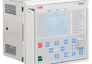
A logical device is not the breaker or the transformer. It is a group of functions inside an IED. The breaker itself appears as an XCBR logical node. Also, IEC 61850 does not use the Common Information Model (CIM). CIM is a different standard, IEC 61970 and IEC 61968, for control-centre software. The two models can be mapped to each other, but they are separate.
MMS, GOOSE and sampled values
The data model says what the data is. The communication services say how it moves. IEC 61850 uses three main services. The figure below shows each one.
MMS, the Manufacturing Message Specification, is an older ISO standard (ISO 9506). IEC 61850-8-1 maps the abstract services onto it. MMS runs over TCP/IP on the station bus, the network at station level. It works as client/server. The client, such as the station HMI or the gateway, asks. The IED, the server, answers. MMS carries reports of changed values, control commands, settings, event logs and file transfers. A breaker command uses select-before-operate: the client first selects the breaker, then sends the operate command. This guards against a wrong command. MMS is reliable, but it is not built for millisecond timing.
GOOSE, the Generic Object-Oriented Substation Event, is for fast messages. It works as publisher/subscriber. One IED publishes a message, and every IED that needs it subscribes. GOOSE does not use TCP/IP. It goes straight into an Ethernet frame (layer 2) as a multicast, so one message reaches many devices at once. A VLAN priority tag lets switches send it ahead of normal traffic. Typical uses are trips, breaker-failure signals and interlocks.
IEC 61850-5 sets speed limits for each type of message. The limit is the transfer time: the time from the sending function to the receiving function, including both devices' communication processing and the network. A trip is a "type 1A" message. For the strictest class, TT6, its transfer time must be 3 ms or less. Some distribution uses allow 10 ms. This is the same speed range as a hard-wired contact.
GOOSE has no acknowledgement. The receiver never says "got it". So how does the publisher make sure the message arrives? It repeats it. The slider below shows the scheme.
The gap doubles after each copy until it reaches the heartbeat time T0 = 1 s. This doubling curve is a common choice. The real values are set when the IED is configured.
When the data changes, the IED sends a new message at once. It adds one to the state number (stNum). Then it repeats the same message quickly, with a growing gap. Each copy adds one to the sequence number (sqNum). When things are quiet, it still sends a heartbeat copy every second or so. Each message also carries a "time allowed to live". If no new copy arrives in that time, the subscriber raises an alarm. So a broken link is found within seconds, not at the next fault.
Sampled values (SV) carry measurements. A merging unit sits near the current and voltage transformers. It samples the currents and voltages and publishes them as a stream on the process bus. Like GOOSE, SV is a layer-2 multicast. The first common profile, called 9-2LE, uses 80 samples per cycle for protection. That is 4000 samples per second at 50 Hz and 4800 at 60 Hz. The newer standard IEC 61869-9 uses 4800 samples per second for protection and general metering, at both 50 and 60 Hz, and 14,400 for power quality.
Each SV stream uses a few megabits per second. So a busy process bus needs careful network design.
Each level does not have "its own" protocol. MMS is not a process-level protocol, and sampled values are not a station-level protocol. MMS mainly runs on the station bus. Sampled values run on the process bus. GOOSE can run on both. Also, the standard's name for the measurement stream is "sampled values" (SV). "SMV" is an informal name.
Station, bay and process levels
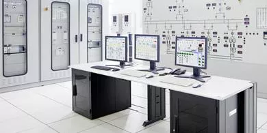
IEC 61850 describes a substation in three levels. Two networks join them. The figure below shows a small substation with three bays. A bay is one circuit, such as a feeder or a transformer, with its own breaker and switches.
- Process level. This is the primary plant: breakers, disconnectors, and current and voltage transformers. In a digital substation, merging units and breaker IEDs sit here. They turn analogue signals and breaker contacts into network messages.
- Bay level. This is where protection relays and bay controllers sit, one set per bay. They take decisions: when to trip, and whether a switch may move.
- Station level. This is the station HMI, the gateway to the control centre and the engineering PC. The HMI, or human-machine interface, is the operator screen. The gateway passes data to the utility's SCADA system, often over IEC 60870-5-104 or DNP3.
The station bus joins the station level and the bay level. It carries MMS and GOOSE. The process bus joins the bay level and the process level. It carries sampled values and GOOSE. Many substations today have a station bus but still use copper at the process level. Adding a process bus is the step that makes a substation fully "digital".
Time synchronisation
Every event needs a correct time stamp. Otherwise we cannot tell which relay tripped first. Sampled values need even better timing. A relay that compares currents from two merging units must know that the samples were taken at the same instant.
- SNTP, the Simple Network Time Protocol, gives about 1 ms accuracy. That is enough for event time stamps.
- PTP, the Precision Time Protocol of IEEE 1588, gives much better accuracy. IEC/IEEE 61850-9-3 is its "power utility profile". It aims for better than 1 µs, even after the time signal passes through 15 network switches. A GPS clock usually acts as the grandmaster, the master time source.
The figure below shows a real system from one vendor. It has the same three levels, with redundant parts at the station level.

SCL files and the engineering workflow
The Substation Configuration Language (SCL) is defined in IEC 61850-6. It is a set of XML files. They describe the substation, the IEDs, the network and every message between them. Because the format is standard, a tool from one maker can read a file from another. The table below lists the file types.
| File | Full name | What it holds |
|---|---|---|
| SSD | System Specification Description | The single-line diagram and the functions needed. No IEDs yet. |
| ICD | IED Capability Description | What one type of IED can do. Supplied by the vendor. |
| SCD | Substation Configuration Description | The whole substation: all IEDs, the network and every GOOSE and SV link. |
| CID | Configured IED Description | One IED's part of the SCD, ready to load into that IED. |
| IID | Instantiated IED Description | One configured IED, sent back from the IED tool to the system tool (Edition 2). |
| SED | System Exchange Description | The interface between two projects, such as both ends of a line (Edition 2). |
A project moves through these files in four steps.
1Specify the substation: SSD
We draw the single-line diagram and list the functions each bay needs. The tool saves this as an SSD file. It has no IEDs in it yet.
2Collect the ICD files
Each vendor supplies an ICD file for its IED. It lists everything the IED can do: its logical nodes, data and services.
3Design the system: SCD
The system configurator joins the SSD and the ICD files. We name the IEDs, set IP addresses and draw the GOOSE and SV links. The result is one SCD file.
4Load each IED: CID
The vendor tool takes its IED's part of the SCD and makes a CID file for download. In Edition 2, changes made in the IED tool go back as an IID file.
The SCD file becomes the single record of the system. Later changes start from it, not from each IED. This is a big change from hard-wired work, where the drawings and the wiring could slowly drift apart.
The ICD files are like product data sheets. The SSD is the architect's plan. The SCD is the full construction drawing, with every part placed and connected. Each CID is the work order for one installer.
Redundancy and cyber security
Once trips travel over Ethernet, the network becomes part of the protection system. It must not fail, and it must not be attacked.
Redundancy: PRP and HSR
Ordinary network recovery methods, such as the rapid spanning tree protocol, can take from milliseconds to seconds to reroute after a fault. That is too slow for a trip or a sampled-value stream. So IEC 62439-3 defines two methods with zero switch-over time. The figure below shows both.
- PRP, the Parallel Redundancy Protocol, uses two separate networks, LAN A and LAN B. Each device sends every frame on both. The receiver keeps the first copy and drops the second.
- HSR, High-availability Seamless Redundancy, uses a ring. Each device sends every frame both ways round the ring. If the ring breaks at one point, the other copy still arrives. HSR needs no separate switches, but each device must forward the ring traffic.
Devices without PRP or HSR can join through a RedBox, a redundancy box. PTP time sync can also run over PRP and HSR networks.
Cyber security: IEC 62351
Plain GOOSE and MMS were designed for closed networks. They had no built-in protection. A fake GOOSE message could, in principle, trip a breaker. The IEC 62351 series adds security to these protocols:
- IEC 62351-3 and -4 secure MMS with TLS encryption and authentication.
- IEC 62351-6 secures GOOSE and sampled values. It mainly adds an authentication code, so a receiver can reject a message that did not come from the real publisher.
- IEC 62351-8 adds role-based access control, so each user can do only what their role allows.
Standards are only part of the answer. Good practice also needs network separation, firewalls at the gateway, strict control of engineering laptops and logging of every change.
Worked example: a feeder trip by GOOSE
Let us follow one fault through a real-looking scheme. An 11 kV feeder has a protection IED from vendor A. It holds PTOC (overcurrent) and PTRC (trip conditioning). The breaker is controlled by a breaker IED from vendor B, which holds XCBR. There is no copper trip wire between them, only the process bus.
Here is what happens, with typical times.
- The fault. A cable fault draws a large current. The merging unit streams the samples to the protection IED.
- Decide: about 20 ms. The instantaneous overcurrent element in PTOC1 operates. Op goes true, and PTRC1 sets its trip output, Tr. A fast element typically takes about one cycle, which is 20 ms at 50 Hz.
- Send by GOOSE: 3 ms or less. The IED publishes a GOOSE message with PTRC1.Tr.general = true and a new stNum. The frame is about 200 bytes. On a 100 Mbit/s link it takes only about 16 µs to send, so most of the 3 ms is processing inside the two IEDs.
- Act: about 4 ms. The breaker IED receives the message. Its output contact closes and energises the trip coil. We assume about 4 ms for a normal output contact. Fast solid-state outputs are quicker.
- Open the breaker: about 50 ms. A medium-voltage breaker typically opens and clears the arc in about 2.5 to 3 cycles.
So the GOOSE path takes about 20 + 3 + 4 + 50 = 77 ms. The figure below compares this with two hard-wired paths.
A direct hard-wired trip, from the relay contact straight to the trip coil, takes about 20 + 4 + 50 = 74 ms. But many schemes put an auxiliary trip relay in the path, for example to trip several breakers at once. A fast auxiliary relay adds about 5 to 10 ms. With 8 ms, the total is about 82 ms.
So GOOSE is not slower than copper. It adds about 3 ms, about the same as one auxiliary relay. And it brings two things copper cannot. The link is supervised all the time, through the heartbeat. And one GOOSE message can reach many subscribers at once, such as breaker-failure protection and the bay controller, with no extra wiring.
The 3 ms limit is not the time to clear the fault. It is only the transfer time of the message. The protection decision and the breaker opening come on top. The breaker is still the slowest part of the chain.
Where IEC 61850 is used, and its editions
IEC 61850 began in substations, but it has grown well beyond them.
- Transmission substations. Large multi-vendor sites gain the most from a common model. Many new transmission substations now use a station bus, and some also use a process bus.
- Distribution substations. Utilities use GOOSE for fast schemes, such as busbar blocking and automatic transfer, and to cut wiring in small sites.
- Power plants. Hydro plants have their own logical nodes in IEC 61850-7-410. Wind farms use IEC 61400-25, which is based on IEC 61850.
- Distributed energy and the smart grid. IEC 61850-7-420 models solar, batteries and other distributed energy resources. This helps connect renewables to the grid.
- Between substations and to the control centre. Technical reports IEC 61850-90-1 and 90-2 extend the standard to links between substations and to control centres.
- Industry. Large plants, such as refineries, mines and data centres, use it for their high- and medium-voltage switchgear.
Take a typical upgrade of a large city substation. The utility replaces old relays and RTUs with IEC 61850 IEDs from more than one vendor. Operators get real-time data and remote control through the HMI and SCADA. Maintenance teams get detailed diagnostics, and they can find a failing device before it causes an outage. Copper wiring falls, and future changes become file edits.
There are challenges too. The first project needs new skills: networking, SCL tools and testing with GOOSE and SV simulators. Older devices must be joined through gateways or proxies. And a mixed-vendor system must be tested as a whole. The best way to learn is hands-on: configure two IEDs from different vendors in a small test project, and watch the GOOSE messages with a network analyser.
Edition 1, Edition 2 and Edition 2.1
- Edition 1 was published from 2003 to 2005. Its title was "Communication networks and systems in substations". It set the data model, the services and SCL.
- Edition 2 followed from about 2009 to 2011. Its title became "Communication networks and systems for power utility automation", because the scope now went beyond substations. It fixed many interoperability problems found in Edition 1. It added new logical nodes, test and simulation modes, and the IID and SED files.
- Edition 2.1 is a set of amendments published around 2018 to 2020. It collects many corrections and clarifications. Most new IEDs today support Edition 2 or 2.1.
When we mix devices of different editions, we must check that the SCL tools and the IEDs can work together. This is one of the most common causes of trouble on site.
Key takeaways
- IEC 61850 is a family of standards for substation automation. It lets IEDs from different makers work together and replaces most copper wiring with Ethernet.
- The data model goes from physical device to logical device, logical node (such as XCBR or PTOC), data object and data attribute.
- MMS is client/server for monitoring and control. GOOSE is fast layer-2 multicast for trips, limited to 3 ms for the strictest trip class. Sampled values stream measurements at 4000–4800 samples per second for protection.
- GOOSE has no acknowledgement. It repeats each new message with a growing gap, then sends a heartbeat, so a lost link is detected.
- SCL files (SSD, ICD, SCD, CID, IID, SED) describe the system. PRP and HSR give zero switch-over redundancy, PTP gives sub-microsecond time, and IEC 62351 adds security.
- A GOOSE trip is as fast as a hard-wired one. The breaker itself is still the slowest part of fault clearing.
This guide gave the full picture of IEC 61850. To see where it fits, we suggest reading about the substation itself, the SCADA systems it reports to and the older serial protocols it replaces. The guides below go deeper.
Related guides on Electrical Blog:
Pingback: Smart grid vs traditional power system explained