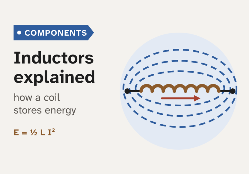
This beginner’s guide explains what an inductor is, how it stores energy and resists changes in current, and how to choose one, with simple diagrams and a live demo.
Quick answer: An inductor is a coil of wire that stores energy in a magnetic field. It resists any change in the current through it: v = L·di/dt. So it passes steady DC easily but opposes AC more and more as the frequency rises (XL = 2πfL). Its inductance L, in henries, depends on the turns, the coil size and the core. Inductors are used in filters, switch-mode power supplies, chokes and line reactors.
What is an inductor?
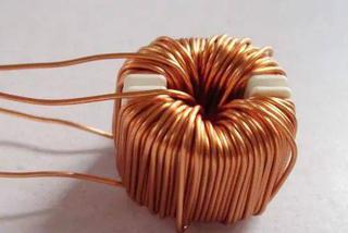
An inductor is a passive component. Passive means it needs no power supply of its own. In its simplest form it is a coil of wire, usually copper. The coil may be wound on air, or on a core, a piece of magnetic material inside or around the coil.
When current flows in the coil, it makes a magnetic field. The field stores energy. And the coil resists any change in its current. These two facts explain almost everything an inductor does. So why does a coil of wire fight a change in current, when a straight wire does not?
We measure this effect with the inductance, L. Its unit is the henry (H). A coil has 1 H when a current change of 1 ampere per second makes 1 volt across it. Real parts range from nanohenries (nH) in radio circuits to henries in large mains chokes. Another way to define L is the flux linkage per ampere: L = NΦ ÷ I, where N is the number of turns and Φ is the magnetic flux, the amount of field through the coil.
Inductors have other names too. A choke is an inductor used to block AC or noise. A reactor is a large inductor in a power system. A transformer looks similar but has two or more windings. It moves energy from one winding to another through mutual inductance, the field of one coil linking the other. An inductor has one winding and uses its own field, which we call self-inductance.
The idea is old. Michael Faraday used an iron ring with two coils to discover electromagnetic induction in 1831. Joseph Henry in the USA published his work on self-induction in 1832. The unit of inductance was named after him in 1893.
How an inductor resists a change in current
Two laws explain the behaviour. Faraday's law says that a changing magnetic flux through a coil induces a voltage, also called an EMF (electromotive force), in that coil. Lenz's law gives the direction: the induced voltage always opposes the change that made it.
Now put these together. When the current in a coil rises, its own field rises. The changing field induces a voltage that pushes against the rise. When the current falls, the induced voltage pushes to keep it flowing. The animation at the top of the page shows this push-back as a red arrow. In one short formula:
v = L · di/dt
Here v is the voltage across the inductor and di/dt is the rate of change of current, in amperes per second. The voltage depends on how fast the current changes, not on how big it is. The figure below shows this for a 10 mH coil.
So an inductor does not stop current. It stops sudden changes in current. The current through an inductor cannot jump from one value to another in zero time, because that would need an infinite voltage.
Think of a heavy flywheel. It is hard to start, and once it spins it is hard to stop. But at a steady speed it needs almost no push. Current in an inductor behaves the same way. The inductance is like the mass of the flywheel.
Inductors with DC. When we switch a DC supply onto a coil and a resistor, the current rises along a curve. It reaches 63% of its final value after one time constant, τ = L ÷ R. After about 5τ it is practically at its final value, V ÷ R. From then on the current is steady, so di/dt = 0 and the ideal inductor has no voltage across it. Only the resistance of the copper winding is left. This is why we say an inductor "passes DC". Try the demo below.
Supply 12 V, switched on at time zero. The coil is treated as ideal, with its winding resistance included in R. The current is i = (V/R)·(1 − e−t/τ). The yellow dot marks t = τ, where i reaches 63% of V/R.
Inductors with AC. With AC, the current changes all the time. So the coil pushes back all the time, and the faster the change, the harder it pushes. We look at this in the AC section below.
Energy stored in the magnetic field
It takes energy to build the magnetic field. While the current rises, the source does work against the push-back voltage. That energy is not lost. It sits in the field:
E = ½ · L · I²
Here E is in joules, L in henries and I in amperes. For example, a 100 mH relay coil carrying 0.5 A stores ½ × 0.1 × 0.5² = 12.5 mJ. The energy grows with the square of the current, so doubling the current gives four times the energy.
An ideal inductor does not turn this energy into heat. It gives it back when the current falls. In an AC circuit the energy flows into the field and back out twice in every cycle. This back-and-forth flow is called reactive power. The only real losses come from the winding resistance and from the core.
But the stored energy must go somewhere when we open a switch. The current tries to keep flowing, so v = L·di/dt becomes very large. If our 0.5 A coil were cut off in 1 µs, the formula gives 0.1 × 0.5 ÷ 0.000001 = 50 000 V. In practice the voltage rises until something breaks down, often as a spark across the switch contacts. This is why a switch can spark when it opens an inductive circuit.
Driving a relay coil or solenoid from a transistor with no path for the current at switch-off. The voltage spike can destroy the transistor. A flyback diode across the coil gives the current a safe path, so it dies away with the time constant L ÷ R. Contactors use RC snubbers or varistors for the same job.
What sets the inductance: turns, size and core
The inductance depends only on the coil's shape and its core, not on the circuit around it. For a long, thin coil, a solenoid, a good estimate is:
L = µ₀ · µr · N² · A ÷ l
- N is the number of turns. L grows with N², so twice the turns gives four times the inductance.
- A is the cross-section area of the coil, in m².
- l is the length of the coil, in m.
- µ₀ is the permeability of free space, about 1.257 × 10⁻⁶ H/m (4π × 10⁻⁷).
- µr is the relative permeability of the core: how much easier it carries magnetic flux than air. Air has µr = 1.
For example, take 100 turns on a 1 cm diameter former, 5 cm long, with an air core. The area is 7.85 × 10⁻⁵ m². So L ≈ 1.257 × 10⁻⁶ × 100² × 7.85 × 10⁻⁵ ÷ 0.05 ≈ 20 µH. The formula slightly overestimates a short coil, so the real value is a little lower.
A magnetic core with a high µr raises L a lot. But a core brings two limits. It has losses at high frequency. And it can saturate: above a certain flux density, measured in tesla (T), the core cannot carry more flux. Its µr then drops towards 1, and so does the inductance. The figure below compares four common cores.
- Air core. No core losses and no saturation, so L stays constant. But we need many turns for a useful L. Used in radio-frequency circuits.
- Ferrite. A ceramic of iron oxide mixed with manganese and zinc (MnZn) or nickel and zinc (NiZn). It has high resistance, so eddy-current losses are low even at hundreds of kilohertz. MnZn suits power supplies. NiZn suits higher frequencies and noise filters.
- Iron powder and other powder cores. Tiny insulated metal grains pressed together. The gaps between grains act as a distributed air gap, so µr is low but the core handles a large DC current before it saturates.
- Laminated iron. Thin sheets of silicon steel, insulated from each other to limit eddy currents. Saturation flux density is high, but losses rise quickly with frequency, so it is used at 50 or 60 Hz.
Power inductors on ferrite usually have a small air gap in the core. The gap lowers L a little. But it stores most of the energy and lets the part carry much more current before it saturates.
So the inductance of a cored part is not quite constant. It falls as the current rises, slowly at first and then fast near saturation. The figure below shows two typical shapes.
A core is like a sponge that soaks up magnetic flux. A dry sponge takes in water easily. A full sponge takes in no more, and any extra water just runs off. A saturated core behaves the same way: extra current adds almost no extra flux, so the inductance collapses.
Inductors in AC circuits
With AC the current changes all the time, so the inductor pushes back all the time. We call this opposition inductive reactance, XL. It is measured in ohms, like resistance:
XL = 2π · f · L
Here f is the frequency in hertz. XL rises in a straight line with frequency. At DC (f = 0) it is zero. A 10 mH inductor has 3.1 Ω at 50 Hz, 31 Ω at 500 Hz and 63 Ω at 1 kHz. A 10 µH inductor has only 3 mΩ at 50 Hz, but 31 Ω at 500 kHz. This is why small inductors are useful in fast switching circuits.
Reactance is not resistance. A resistor turns energy into heat. An ideal inductor only stores energy and returns it. In an inductor the current lags the voltage by 90°, a quarter of a cycle. A real coil also has winding resistance R. Its total opposition, the impedance, is Z = √(R² + XL²).
A capacitor does the opposite of an inductor. Its reactance, XC = 1 ÷ (2πfC), falls as the frequency rises. When we combine both, there is one frequency where XL = XC. This is the resonant frequency, f₀ = 1 ÷ (2π√(LC)). For 10 mH and 100 µF it is about 159 Hz. At resonance a series LC circuit has its lowest impedance. A parallel LC circuit, called a tank circuit, has its highest impedance. Radio tuners use this to pick one frequency.
Inductors in series and in parallel. When the coils do not share their magnetic fields, they combine like resistors:
- Series: L = L1 + L2 + … The same current flows in each. Two 10 mH coils in series give 20 mH.
- Parallel: 1/L = 1/L1 + 1/L2 + … The same voltage is across each. Two 10 mH coils in parallel give 5 mH.
If the coils are close together, their fields link and mutual inductance changes the result. Then the total can be higher or lower, depending on how the coils are wound. To avoid this, keep the coils apart, shield them or set them at right angles.
How to read inductor ratings
A datasheet gives more than the inductance. For power work, the current ratings matter just as much. The table below lists the main ratings, with values for a typical shielded 10 µH power inductor.
| Rating | What it tells us | Example |
|---|---|---|
| Inductance L | Value at low current, with a tolerance | 10 µH ±20% |
| Isat | Peak current where L has dropped by a set amount (often 20% or 30%) | 3.8 A |
| Irms (heating current) | DC or RMS current for a set temperature rise, often 40 °C | 3.2 A |
| DCR | Resistance of the copper winding; sets the I²R loss | 30 mΩ |
| SRF | Self-resonant frequency; above it the part stops acting as an inductor | 30 MHz |
Note the two current ratings. Isat is about the core: above it, L falls. Irms is about heat in the copper: the loss is I² × DCR. The current must stay below both. Makers define them differently, for example a 10%, 20% or 30% drop in L, so we read the test conditions.
The SRF comes from the small capacitance between the turns. Above the SRF, the part acts like a capacitor. So we use an inductor well below its SRF. The Q factor, XL ÷ R at a given frequency, tells us how close the part is to an ideal inductor. A high Q matters in filters and tuned circuits.
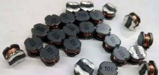
Small parts are marked with a three-digit code in microhenries. The first two digits are the value, and the third is the number of zeros. So 100 means 10 µH and 101 means 100 µH. The letter R marks a decimal point, so 4R7 means 4.7 µH. Some small through-hole inductors use colour bands, read like resistor bands, also in microhenries.
Worked example: a buck converter inductor
A buck converter is a DC-DC converter that steps a voltage down. A fast switch chops the input, and an inductor and capacitor smooth the result. The inductor is the heart of it. It stores energy while the switch is on and delivers it to the load while the switch is off.
Our design: 12 V in, 5 V out, 2 A load, switching at 500 kHz. The four cards below choose the inductor.
1Find the duty cycle
For an ideal buck converter, the switch is on for D = Vout ÷ Vin of each cycle. Here D = 5 ÷ 12 ≈ 0.42.
2Pick the ripple current
A common rule is a peak-to-peak ripple ΔI of 20% to 40% of the load current. We take 30% of 2 A, so ΔI = 0.6 A.
3Calculate L
During the on-time, 7 V drives the current up by ΔI. This gives L ≈ 9.7 µH. We round up to the standard value of 10 µH.
4Check Isat, Irms and DCR
With 10 µH, ΔI = 0.58 A and the peak is 2.29 A. A part with Isat = 3.8 A, Irms = 3.2 A and DCR = 30 mΩ fits well.
The figure below shows the result. The inductor current is a triangle around the 2 A load current. While the switch is on, v = 12 − 5 = 7 V across the inductor, so the current rises at 7 V ÷ 10 µH = 0.7 A per µs. While it is off, v = −5 V and the current falls at 0.5 A per µs.
Two quick checks. The stored energy at the peak is ½ × 10 µH × 2.29² ≈ 26 µJ. That is tiny, but it is handed over 500 000 times a second. And the reactance of 10 µH at 500 kHz is 2π × 500 000 × 10 × 10⁻⁶ ≈ 31 Ω. That is why it smooths the switching ripple so well.
Choosing an inductor by its inductance alone. A 10 µH part with an Isat of 2 A would saturate at our 2.29 A peak. Its inductance would collapse, the ripple would jump and the switch could fail. Always check Isat against the peak current, and Irms against the RMS current, with some margin for start-up and overload.
Where inductors are used
Inductors appear in almost every piece of electronic and electrical equipment. The figure below shows four common jobs.
- Filters. An inductor in series and a capacitor to ground form an LC filter. The inductor opposes the AC ripple, and the capacitor shorts it to ground. Power supplies, audio crossovers and inverter outputs use LC filters.
- Chokes and ferrite rings. A common-mode choke is two windings on one core. It blocks noise that flows the same way on both wires, but lets the normal signal or supply current through. A ferrite ring on a cable does the same job. Ferrite becomes lossy at high frequency, so it turns the noise energy into a little heat.
- Switch-mode power supplies (SMPS). Buck, boost and flyback converters all use an inductor, or a coupled inductor, to store energy in each cycle.
- Line reactors. These are three-phase inductors in front of a variable frequency drive (VFD). Their size is given as a percentage impedance, often 3% or 5%. A 3% reactor helps with nuisance trips and voltage spikes. A 5% reactor also reduces input harmonics more. For a 400 V, 50 A drive, 3% is about 0.14 Ω per phase, or about 0.44 mH.
- Tuned circuits. An inductor and a capacitor in parallel select one frequency in radio receivers and oscillators.
A current transformer (CT) also looks like a coil on a ring core. But it is a transformer, not an inductor. Its secondary must always be connected to a meter, a relay or a shorting link. An open CT secondary can produce a dangerous high voltage.
Replacing a failed inductor with a 0 Ω resistor or a wire link, or with any part of the same size. The filter or converter then stops working as designed. A replacement needs the same inductance and at least the same Isat, Irms and SRF, and a similar DCR and shielding.
Key takeaways
- An inductor is a coil that stores energy in a magnetic field: E = ½·L·I².
- It resists changes in current: v = L·di/dt. The current cannot jump, and opening an inductive circuit causes a voltage spike.
- Inductance depends on turns, area, length and core: L = µ₀·µr·N²·A ÷ l. Cored parts lose inductance when they saturate.
- With DC, current rises with the time constant τ = L/R, then only the winding resistance remains. With AC, the reactance XL = 2πfL rises with frequency.
- Series inductors add. Parallel inductors combine like parallel resistors, if their fields do not link.
- Choose a part by L, Isat, Irms, DCR and SRF, not by inductance alone.
Next, we suggest looking at how inductance fits beside resistance and capacitance in power circuits, and why the grid cares about reactive power. The guides below go deeper.
Related guides on Electrical Blog: