
What is Current Transformer?
A current transformer is an instrument transformer also known as CT, used to step down the line current of an electrical circuit so that it can be used in the revenue meters and in the protection relay. As we know typically the line currents are high enough. So to safely use them in the metering and protection circuit a CT is used.
It consists of two parts: a primary winding and a secondary winding just like a typical transformer. The current enters the primary winding (producing flux in the core), and then is induced into the secondary by the changing magnetic field, producing current which flows through its own windings. This article will explain the current transformer’s basic principle, construction, and usage.
Purpose of Current Transformer in Electrical Circuits:
A current transformer is used in an electrical circuit for three main reasons-
- To reproduce the primary current to a lower level so that it can be used in the secondary circuit
- To insulate the control and metering circuits
- Step down the currents to the standardized value for the relays and the meters
Basic Principle and Construction of Current Transformer:
The basic principle of a current transformer is similar to the current flow in a solenoid. In the current transformer, current flows through the primary coil which produces flux in the core and induces a voltage into secondary winding proportional with current flowing through it. The current and turns ratio relationship in a current transformer is as follows.
I_p \times N_p = I_s \times N_s
where:
I_p = Primary  \ Current \\
N_p = Primary \ Turns\  Number \\
I_s = Secondary  \ Current \\
N_s = Secondary \ Turns\  Number \\
A current transformer consists of two parts, the primary winding (Np) , and secondary winding (Ns). The core contains insulation between each turn so that no direct current can flow through it from one side to another but only alternating current.
Here we have a primary winding Np and a secondary winding Ns. The current Ip flowing in the primary winding produces a magnetic flux ψ1 which induces a current Is in the secondary. The ratio of Np to Ns is called the “turns ratio” and is expressed as “a”. For example if Ip = 500A and Is = 5A then a=5/500=1/100 or 1% turns ratio.


Types of Current Transformer:
Based on construction there are three types of current transformers, they are
- Wound/Block type CT:

- Window/Ring Type CT :

- Core type CT: This current transformer consists of a separate secondary winding with no primary winding and it can be installed directly between current carrying conductors without disconnecting them from supply. Using this current transformers, there will not be any change in voltage or current magnitude of main
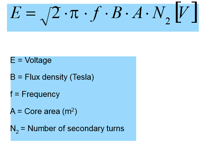
Current Transformer EMF equation
If the flux is sinusoidal then the EMF is expressed as the below equation
Typical designs of High Voltage CTs

Current Transformer -AIS and GIS design

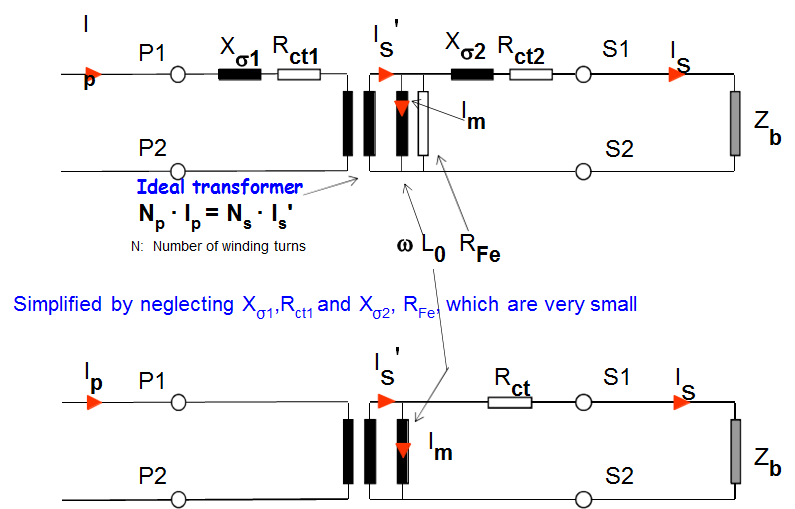
Current Transformer -Equivalent diagram
Current Transformer Rating Plate Explained

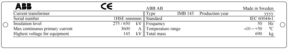
- Rated insulation level – primary winding: 275 kV
- Lightning impulse withstand : 675 kV pk
- Max continuous primary current: 3600 A
- Highest voltage for equipment : 145 kV
- Insulation class: All classed immersed in oil and hermetically sealed according to table 2 in IEC 60044-1
- Rated frequency 50 Hz
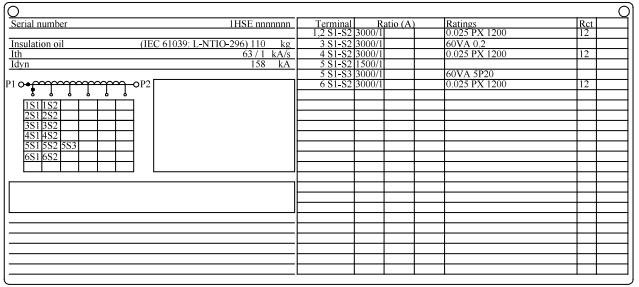
- Rated short term thermal current for 1s : 63 kA rms
- Rated dynamic current : 158 kA pk
CT Accuracy Class
Examples: 30VA, 5P20
30VA, 5P20
30VA rated burden at rated secondary current
5 total error in % at accuracy limit and rated burden
P protection class
20 minimum multiple of rated secondary current at which the accuracy limit is reached with the rated burden
Special Type Current Transformers:
Clamp-on Current Transformer
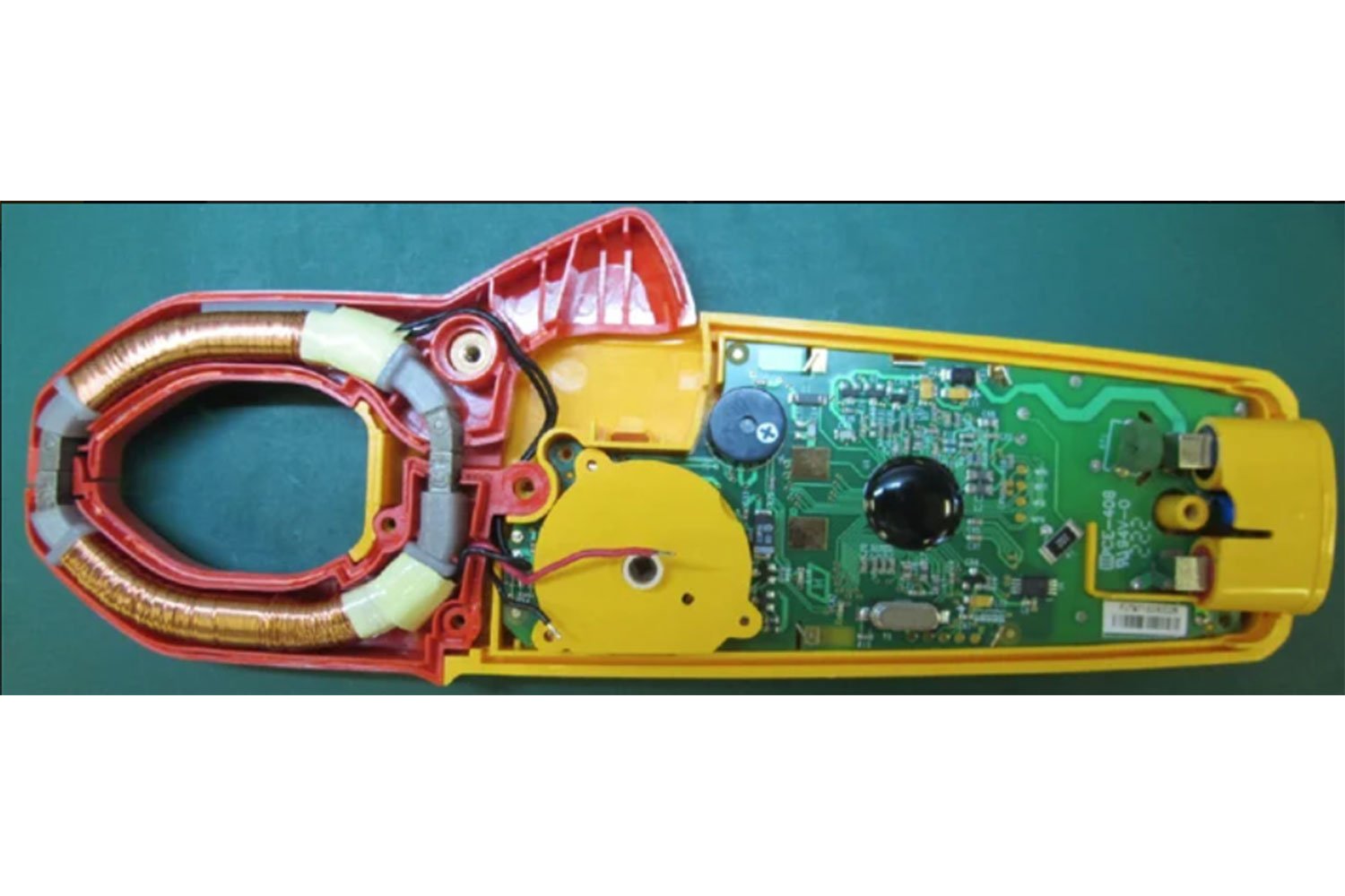
Clamp meters are equipped with jaws of ferrite iron. They are individually wrapped by coils of copper wire. This coil that is wrapped around the jaws serves as a secondary winding of the CT. As the current flows through the primary winding, an alternating magnetic field is generated which causes an EMF to be induced in the secondary winding. As a result, a small current flows through the secondary winding which then measured by the ammeter.
Optical Current Transformer (Fiber Optic Current Sensor FOCS by ABB)
An optical current transformer or fiber-optic current sensor is a unique product that uses the Faraday effect to measure electric currents with great sensitivity and accuracy. It measures magnetic fields by measuring the change in the speed of light caused by a changing magnetic field. This sensor doesn’t suffer from the ct saturation effect.

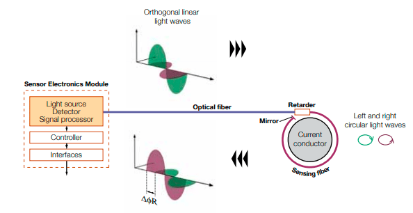

It can be used in harsh environments where other types of amperometric or potentiometric current sensors cannot be used.
References:
- https://library.e.abb.com/public/94c2ba5a2f381077c1257df000504e0c/1HSM%209543%2040-00en%20IT%20Application%20Guide%20Ed4.pdf
- https://www.fluke.com/en-us/learn/blog/clamps/inside-current-transformer-ac-clamp-meters
- https://www.linkedin.com/pulse/specifying-current-transformers-protection-purposes-bryan-johnson/
Pingback: Electrical Substation - Basics - Electrical Blog