An induction motor refers to a motor that relies on electromagnetic the stator and rotor to induce a current in the rotor to realize electromechanical energy conversion. The stator of the induction motor consists of three parts: the stator core, the stator winding, and the frame.
The rotor consists of a rotor core, a rotor winding, and a rotating shaft. The rotor core is also a part of the primary magnetic circuit, generally made of silicon steel sheets with a thickness of 0.5mm. The core is fixed on the rotating shaft or rotor bracket. The appearance of the entire rotor is cylindrical. Rotor windings are divided into two categories: squirrel type and wound type.
Under normal circumstances, the rotor speed of the induction motor is always slightly lower or slightly higher than the speed of the rotating magnetic field (synchronous speed), so the induction motor is also called an “asynchronous motor. “
When the load on an induction motor changes, the rotor’s rotational speed, and slip rate also change. This means that the electromotive force, current, and electromagnetic torque in the rotor conductor also vary to meet the needs of the load. Depending on whether the slip rate is positive or negative and how big it is, an induction motor can operate in three different ways: a motor, a generator, or an electromagnetic brake.
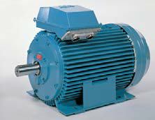
Induction motor structure
The stator of the induction motor consists of three parts: the stator core, the stator winding, and the frame. The stator core is part of the primary magnetic circuit. The iron core is made of silicon steel sheets with a thickness of 0.5mm to reduce eddy current and hysteresis loss caused by the exciting current and the rotating magnetic field. For motors with larger capacity, silicon steel sheets are coated with insulating paint on both sides as insulation between sheets. The small stator core is stacked with silicon steel sheets, pressed into a whole, and then fixed in the machine base; the medium and large stator cores are made up of fan-shaped punching pieces. In the inner circle of the stator core, many grooves of the same shape are evenly punched to embed the stator windings. Small induction motors usually use semi-closed slots, single-layer (scattered) windings wound with high-strength enameled wires, and slot insulation is placed between the coil and the iron core. The semi-closed slot can reduce the primary magnetic circuit’s reluctance and excitation current, but it is inconvenient to insert the wire. Medium-sized induction motors typically use half-open slots. Large high-voltage induction motors use open slots for easy wiring. In order to obtain better electromagnetic performance, medium and large induction motors use double-layer short-distance windings.
The rotor consists of a rotor core, a rotor winding, and a rotating shaft. The rotor core is also a part of the primary magnetic circuit, generally made of silicon steel sheets with a thickness of 0.5mm. The core is fixed on the rotating shaft or rotor bracket. The appearance of the entire rotor is cylindrical. Rotor windings are divided into two types: squirrel type and wound type.
Squirrel Rotor
The cage winding is a self-closing winding. It consists of a bar inserted into each rotor slot, and annular end rings at both ends. If the iron core is removed, the entire winding is shaped like a “circular cage,” called a cage winding. . To save copper and improve productivity, small cage motors generally use cast aluminum rotors; for medium and large motors. Since the quality of cast aluminum is not easy to guarantee, a structure in which copper bars are inserted into the rotor slots and end rings are welded on both ends is adopted. The cage induction motor is simple in construction and easy to manufacture and is an economical and durable motor. So it is very widely used.
Wound Rotor
The slot of the wound rotor is embedded with a three-phase winding composed of insulated wires, and the three outgoing wires of the winding are terminated.
To the three collector rings arranged on the rotating shaft and then lead out through the brush. The characteristic of this rotor is that an external resistance can be connected to the rotor winding to improve the motor’s starting and speed regulation performance.
Compared with the squirrel-type rotor, the wound rotor has a slightly more complicated structure and a higher price. Therefore, it is only used when the starting current is required to be minor, the starting torque is ample, or the need to be dispatched.
Operating Principle
The induction motor uses the principle of electromagnetic induction to generate a rotating magnetic field through the three-phase current of the stator. It interacts with the induced current in the rotor winding to generate electromagnetic torque for energy conversion. Under normal circumstances, the rotor speed of the induction motor is always slightly lower or slightly higher than the speed of the rotating magnetic field (synchronous speed), so the induction motor is also called an “asynchronous motor.
When the load on an induction motor changes, the rotor’s rotational speed, and slip rate also change. This means that the rotor conductor’s electromotive force, current, and electromagnetic torque also vary to meet the needs of the load. Depending on whether the slip rate is positive or negative and how big it is, an induction motor can operate in three different ways: a motor, a generator, or an electromagnetic brake.
When the rotor speed is lower than the speed of the rotating magnetic field (ns>n>0), the slip is 0<s<l. According to the right-hand rule, the air-gap rotating magnetic field generated by the sub-three-phase current is set to turn counterclockwise. After the rotor conductor “cuts” the air gap magnetic field, it is possible to figure out the direction of the electromotive force. Since the rotor windings are short-circuited, current flows in the rotor conductors. When the rotor-induced current interacts with the magnetic field in the air gap, electromagnetic force and torque are created. The left-hand rule says that the direction of the electromagnetic torque is the same as the direction the rotor is turned, so the electromagnetic torque is the driving torque. At this time, the motor is input from the power grid Power, through electromagnetic induction, mechanical power is output by the rotor, and the motor is in the state of a motor.
If the prime mover drives the motor so that the rotor speed is higher than the rotating magnetic field speed (n>ns), the slip s<0. At this time, the current’s induced, and active component of the current will be opposite to that of the motor state, so the direction of the electromagnetic torque will be opposite to both the rotating magnetic field and the rotor steering, that is, the electromagnetic torque is a braking torque. To make the rotor continue to rotate at a higher speed than the rotating magnetic field. The prime mover’s driving torque must overcome the brake’s electromagnetic torque; at this time, the rotor inputs mechanical power from the prime mover and outputs electrical power through electromagnetic induction, and the motor is in a generator state.
Suppose the rotor is rotated against the direction of the rotating magnetic field by mechanical or other external factors (n<0), the slip ratio s>1. At this time, the relative speed direction of the rotor conductor “cutting” the air gap magnetic field is the same as that of the motor state, so the induced electromotive force and the active component of the current in the rotor conductor are in the same direction as the motor state. The direction of the electromagnetic torque is also the same. However, since the rotation of the rotor is changed, the electromagnetic torque appears as a braking torque for the rotor. At this time, the motor is in the state of electromagnetic braking. On the one hand, it inputs mechanical power from the outside world and at the same time draws electrical power from the grid, both of which become losses inside the motor.
Rated value
Induction motors are rated for:
(1) Rated power P refers to the mechanical power generated by the shaft end when the motor runs in the rated state. In kilowatts (kW).
(2) Stator rated voltage UN: refers to the line voltage that should be applied to the stator winding when the motor is running in the rated state. The unit is volts (v).
(3) The stator rated current IN/” refers to the line current flowing into the stator winding when the motor runs at the rated voltage and the output power reaches the rated power, and the unit is Ampere (A).
(4) The rated frequency fN refers to the power frequency applied to the stator side, and the power frequency in my country is 50 Hz (Hz).
(5) Rated rotation speed nN The rotation speed of the rotor when the motor is running in the rated state, the unit is revolution/min (r/min). In addition to the above data, the power factor, efficiency, temperature rise, rating, etc., of the motor during rated operation are sometimes indicated on the nameplate. Data such as rotor voltage and rotor rated current are often marked for wound motors.
Type
Powerful AC induction motors have slowly evolved into a standard type of motor design characterized by high efficiency and attractive prices. The National Electrical Manufacturers Association ( NEMA) has developed a specification called NEMA A, B, C, and D Motor Types that standardize typical motor characteristics such as starting current, slip, and torque point to suit a variety of different load applications.
Here is a rundown of NEMA motor types:
Type A: Normal starting torque (usually 150-170% of rated), correspondingly high starting current. Limit torque is the highest of all NEMA types. Can handle heavy loads in a short time. The slip is less than or equal to 5%. A typical application is motors for injection molding machines.
Type B: It is the most type of AC induction motor. Its starting torque is similar to Type A but sometimes lower, providing a lower starting current. However, it locks rotor torque in industrial applications and allows starting loads. The slip is less than or equal to 5%. Motor efficiency and full load power factor are relatively high. Typical applications include pumps, fans, and machine tools.
Type C: Provides high starting torque (higher than Types A and B, typically 200% overrated). It is often used to drive heavy starting loads. These motors can run at almost full speed without overloading. The starting current is low. The slip is less than or equal to 5%.
Type D: The motor provides the highest starting torque of all NEMA motor types. Low starting current and full load speed. With a high slip value (5-13%), the motor is suitable for machines with no load change or severe change in the motor speed, such as the energy storage of the flywheel. Many types of sub-categories also include wider slip ranges. This type of motor is generally custom-made.
The speed-torque characteristics of these motors vary. The stator and rotor torque (starting torque) is the minimum torque generated when the rotor stops and is the rated voltage and frequency. Limit torque is the maximum torque before a sudden motor speed reduction occurs at rated speed (rated voltage and frequency). The pull-up torque is the minimum torque, which is generated when the speed of the motor goes from stop to the speed point, at which time the limit torque occurs.
The IEC defines the European and global motor markets have different motor types and specifications. One of the IEC induction motor types, Type N, has operating characteristics comparable to NEMA Types A and B.
Induction Motor Features
1. Induction motors use auxiliary coils and capacitors not only during startup but also during operation. Although the starting torque is not very large, it has a simple structure, high reliability, and high efficiency.
2. It can run continuously.
3. With the load’s size, the motor’s rated speed will also change.
4. It is used in applications that do not require speed braking.
5. Use E-type insulation grade, while UL type motor uses A-type.
6. There are two types of induction running single-phase induction motors and three-phase induction motors.
7. The single-phase motor is an induction motor with high efficiency and low noise.
8. When the single-phase induction motor is running, the torque opposite to the rotation direction is generated, so it is impossible to change the direction in a short time. The direction of rotation should be reversed after the motor has come to a complete stop.
9. The power supply of a single-phase motor includes A (110V 60Hz), B (220V 60Hz), C (100V 50/60Hz), D (200V 50/60Hz), E (115V 60Hz), X (200-240V50Hz), etc.
10. The power supply of the three-phase motor includes U (200V 50/60Hz), T (220V 50/60Hz), S (380-440V 50/60Hz), etc.
The rotor in an induction motor has no specific electrical connection.
Advantage
1) Small and lightweight;
2) It is easy to realize high-speed rotation with speed exceeding 10000r/min;
3) High operating efficiency at high speed and low torque;
4) High torque at low speed and a wide range of speed control;
5) High reliability (solid);
6) Low manufacturing cost;
7) Simplification of the control device;
Disadvantages:
Induction motor causes lagging power factor and slightly poor speed regulation performance.
An induction motor is a kind of asynchronous motor. Since the asynchronous motor is mainly an induction motor, some people directly define the asynchronous motor as an induction motor at the time of definition. But asynchronous motors include induction motors, doubly-fed asynchronous motors, and AC commutator motors.
Pingback: Electric Motor Protection - Types of Faults and Protection Devices Description - Electrical Blog