Inductors are components that convert electrical energy into magnetic energy and store it. The structure of an inductor is similar to that of a transformer but with only one winding. An inductor has a specific inductance, it only resists changes in current flow.
If the inductor has no current flowing, it will try to block the current flow through it when the circuit is on; if the inductor has a current flowing, it will try to maintain the current flow when the circuit is off. Inductors are also called chokes, reactors, and dynamic reactors.
Principle of Inductance
Inductance is the ratio of the magnetic flux of the wire to the current that produces this magnetic flux when an alternating current is passed through the wire, which generates an alternating magnetic flux around the interior of the wire. When a DC current is passed through the inductor, only fixed magnetic lines of force appear around it, which do not change with time, but when an AC current is passed through the coil, there will be magnetic lines of force around it that change with time.
According to Faraday’s Law of Electromagnetic Induction-Magnetic Electricity Analysis, the changing magnetic field lines will generate an induced potential at both ends of the coil, equivalent to a “new power supply.” This induced potential will generate an induced current when a closed loop is formed. It is known from Lenz’s law that the total amount of magnetic lines of force generated by the induced current should try to prevent the changes in the magnetic lines of force.
The change of the magnetic line of force comes from the change of the external alternating power supply, so from the objective effect, the inductance coil has the characteristic of preventing the current change in the alternating current circuit. The inductance coil has characteristics similar to inertia in mechanics and is named “self-induction” in electricity. Usually, sparks will occur when the knife switch is opened or turned on. This self-induction phenomenon produces a very caused by high induced potential.
In short, when the inductive coil is connected to the AC power supply, the magnetic lines of force inside the coil will always change with the alternating current, causing the coil to generate electromagnetic induction. This electromotive force generated by the change of the current of the coil itself is called “self-induced electromotive force.” It can be seen that the inductance is only a parameter related to the number of turns, size, shape, and medium of the coil. It is a measure of the inertia of the inductive coil and has nothing to do with the applied current.
Inductor substitution principle
The inductance coil must be replaced with the original value (the number of turns is equal, and the size is the same).
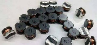
The chip inductors only need to be the same size and can also be replaced by 0-ohm resistors or wires.
Development of Inductors
The most primitive inductor is the iron-core coil used by British Michael Faraday to discover the phenomenon of electromagnetic induction in 1831. In 1832, Joseph Henry of the United States published a paper on the phenomenon of self-induction, and people called the unit of inductance Henry or Henry for short. In the mid-19th century, inductors were used in devices such as telegraphs and telephones. Heinrich Rudolf Hertz in Germany in 1887 and Nikola Tesla in the United States in 1890 used inductors in their experiments are very famous, respectively called Hertz. Coils and Tesla Coils.
The role of inductors
Inductors mainly play the functions of filtering, oscillation, delay, and notch in the circuit, as well as filtering signals, filtering noise, stabilizing current, and suppressing electromagnetic wave interference.
The most common role of inductors in circuits is to form LC filter circuits together with capacitors. Capacitors have the characteristics of “blocking DC and passing AC,” while inductors have the function of “passing DC and blocking AC”:
Direct current: The inductor is in a closed state to the direct current. If the resistance of the inductor coil is not considered, then the direct current can pass through the inductor “unimpeded.” For direct current, the resistance of the coil itself has minimal hindering effect on direct current, so Often ignored in circuit analysis.
Blocking alternating current: When an alternating current passes through the inductive coil, the inductor hinders the alternating current, and the inductive coil’s inductive reactance hinders the alternating current.
If the DC with many interference signals is passed through the LC filter circuit, the AC interference signal will be consumed by the inductance into heat energy. When a relatively pure DC current passes through the inductor, the AC interference signal is also turned into magnetic induction and thermal energy. The inductor’s higher frequency is most easily resisted, which can suppress the higher frequency interference signal.
Inductors have the property of blocking the passage of alternating current and allowing direct current to pass smoothly. The higher the frequency, the greater the coil impedance. Therefore, the primary function of the inductor is to isolate and filter the AC signal or form a resonant circuit with capacitors and resistors.
The structure of the inductor
Inductors are generally composed of skeletons, windings, shields, packaging materials, magnetic cores, or iron cores.
1. Skeleton
The skeleton generally refers to the bracket on which the coil is wound. Some larger fixed inductors or adjustable inductors (such as oscillating coils, choke coils, etc.), most of which are wrapped with enameled wire (or yarn-covered wire) on the skeleton, and then the magnetic core or copper core, iron core, etc. Installed into the inner cavity of the skeleton to increase its inductance. The skeleton is usually made of plastic, bakelite, and ceramics and can be made into different shapes according to actual needs: small inductors (such as color-coded inductors) generally do not use skeletons but directly wind the enameled wire on the magnetic core; hollow inductors The coil (also known as the unwrapped coil or the hollow coil, which is mostly used in high-frequency circuits) does not need a magnetic core, a skeleton, a shield, etc., but is first wound on the mold and then takes off the mold, and the coils are pulled apart by a certain amount of distance.
2. Winding
Winding refers to a group of coils with specified functions, which are the basic components of inductors. There are single-layer andmultilayerr windings. There are two types of single-layer windings: dense winding (conductors are wound one turn after another) and intermediate winding (there is a certain distance between each turn of wires during winding).Multilayerr windings include layered flat winding and random winding, honeycomb winding method, etc.
3. Magnetic core and magnetic rod
Magnetic cores and magnetic rods are generally made of nickel-zinc ferrite (NX series) or manganese-zinc ferrite (MX series).
4. Iron Heart
The core materials are mainly silicon steel sheets, permalloy, etc., and their shapes are mostly “E”.
5. Shield
To prevent the magnetic field generated by some inductors from affecting the regular operation of other circuits and components, a metal screen cover (such as the oscillation coil of a semiconductor radio, etc.) is added to it. Using shielded inductors will increase the loss of the coil and reduce the Q value.
6. Packaging materials
After some inductors (such as color code inductors, color ring inductors, etc.) are wound, the coils and magnetic cores are sealed with packaging materials. The encapsulation material is plastic or epoxy resin.
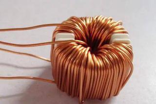
copper coil
Inductance is the ratio of the magnetic flux of the wire to the current that produces this magnetic flux when an alternating current is passed through the wire, which generates an alternating magnetic flux around the interior of the wire. When a DC current passes through the inductor, only fixed magnetic lines of force appear around it, which do not change with time;
However, when an alternating current is passed through the coil, magnetic field lines that change with time will appear around it. According to Faraday’s Law of Electromagnetic Induction—Magnetic Electricity, the changing magnetic field lines will generate an induced potential at both ends of the coil, equivalent to a “new power supply.” When a closed loop is formed, this induced potential will generate an induced current. It is known from Lenz’s law that the total amount of magnetic lines of force generated by the induced current should try to prevent the changes in the magnetic lines of force. The change of the magnetic line of force comes from the change of the external alternating power supply, so from the objective effect, the inductance coil has the characteristic of preventing the current change in the alternating current circuit. The inductance coil has characteristics similar to the inertia in mechanics and is named “self-induction” in electricity. Usually, sparks will occur at the moment when the knife switch is opened, or the knife switch is turned on. caused by high induced potential.
In short, when the inductive coil is connected to the AC power supply, the magnetic field lines inside the coil will always change with the alternating current, causing the coil to generate electromagnetic induction. This electromotive force generated by the change of the coil’s current is called “self-induced electromotive force.” It can be seen that the inductance is only a parameter related to the number of turns, size, shape, and medium of the coil. It is a measure of the inertia of the inductive coil and has nothing to do with the applied current.
Replacement principle:
1. The inductance coil must be replaced with the original value (the number of turns is equal, and the size is the same).
2. The chip inductors only need to be the same size and can also be replaced by 0-ohm resistors or wires.
Classification of Inductors
1. Self-inductor
When current flows through the coil, a magnetic field is generated around the coil. When the current in the coil changes, the magnetic field around it also changes accordingly. The changing magnetic field can cause the coil to generate an induced electromotive force (induced electromotive force) (the electromotive force is used to represent the terminal voltage of the ideal power supply of the active element). It’s self-awareness.
It is an electronic component wound with wire, has a certain number of turns, and can generate a certain amount of self-inductance or mutual inductance. It is often called an inductance coil. To increase the inductance value, improve the quality factor, and reduce the volume, iron cores or magnetic cores made of ferromagnetic substances are often added. The basic parameters of inductors are inductance, quality factor, inherent capacitance, stability, the current passing through, and frequency of use. An inductor composed of a single coil is called a self-inductor, and its self-inductance is also called a self-inductance coefficient.
2. Transformer
When two inductive coils are close to each other, the magnetic field change of one inductive coil will affect the other inductive coil, and this effect is mutual inductance. The size of the mutual inductance depends on the degree of coupling between the self-inductance of the inductive coil and the two inductive coils. The component made using this principle is called mutual inductance.
Characteristics of Inductors
The properties of an inductor are the opposite of those of a capacitor. It has the property of blocking the passage of alternating current and allowing direct current to pass smoothly. When the DC signal passes through the coil, the resistance is the resistance voltage drop of the wire itself. When the AC signal passes through the coil, a self-induced electromotive force will be generated at both ends. The direction of the self-induced electromotive force is opposite to the direction of the applied voltage, which hinders the passage of AC.
Therefore, the characteristics of the inductor are to pass DC and block AC. The higher the frequency, the greater the coil impedance. Inductors often work with capacitors in circuits to form LC filters, LC oscillators, etc. In addition, people also use inductance characteristics to manufacture choke coils, transformers, relays, etc.
Basic uses of inductors
1. The function of inductors is mainly to pass DC and block AC, and it mainly plays the role of filtering, oscillation, delay, and notch in the circuit. The inductive coil has a blocking effect on the alternating current, and the size of the blocking effect is called inductive reactance XL, and the unit is the ohm. Its relationship with inductance L and AC frequency f is XL=2πfL. Inductors can be mainly divided into high-frequency choke coils and low-frequency choke coils. Tuning and frequency selection: the inductance coil and the capacitor are connected in parallel to form an LC tuning circuit. The natural oscillation of the circuit the frequency f0 is equal to the frequency f of the non-AC signal, the inductive reactance and capacitive reactance of the loop are also equal, so the electromagnetic energy oscillates back and forth in the inductor and capacitor, which is the resonance phenomenon of the LC loop. During resonance, the circuit’s inductive reactance and capacitive reactance are equal and opposite. The inductive reactance of the total loop current is the smallest, and the current amount is the largest (referring to the AC signal of f=f0). The AC signal of f is selected.
2. The inductor also has the functions of filtering signals, filtering noise, stabilizing current, and suppressing electromagnetic wave interference. In electronic equipment, some magnetic rings are often seen. This magnetic ring forms an inductor with the connecting cable (the wire in the cable is wound around the magnetic ring for several turns of inductance coils). It is a commonly used anti-interference component in electronic circuits. , High-frequency noise has a good shielding effect, so it is called absorption magnetic ring, usually made of ferrite material, also known as magnetic ferrite ring (referred to as magnetic ring). The magnetic ring has different impedance characteristics at different frequencies. The impedance is minimal at low frequencies, and the impedance of the magnetic ring increases sharply when the signal frequency increases.