Table of Contents
- 1. Resistance
- FAQ:
- Here is how the resistor color code calculator works:
- 2. Inductance
- FAQ:
- Inductive Impedance:
- 3. Capacitance
- FAQ:
- Capacitive Impedance:
1. Resistance
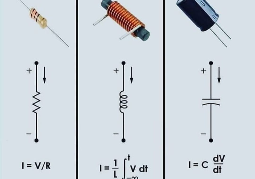
When current flows through a conductor, the conductor’s internal resistance property to hinder the current flow is called resistance. The components that play a blocking role in the circuit are resistors or resistors for short. The primary purpose of the resistor is to step down, divide or divide the current, and it is used as load, feedback, coupling, isolation, etc., in some special circuits.
The symbol of the resistor in the circuit diagram is the letter R. The standard resistance unit is ohms, denoted by R. Commonly used are kiloohm KΩ and megohm MΩ.
IKΩ=1000Ω 1MΩ=1000KΩ
FAQ:
What is an electrical resistor?
An electrical resistor is a passive component that is used in electronic circuits to reduce the flow of electric current. It does this by introducing resistance to the circuit, which causes a voltage drop across the resistor and dissipates energy as heat.
What are electrical resistors used for?
Electrical resistors are used for a variety of purposes, including:
- Dividing voltage
- Adjusting the current in a circuit
- Setting the gain in amplifiers
- Providing a load in a circuit
- Adjusting the impedance in a circuit
- Protecting other components from damage due to excessive current
How are electrical resistors rated?
Electrical resistors are typically rated according to their resistance value, tolerance, and power rating. The resistance value is measured in ohms and indicates the amount of resistance the resistor will introduce to the circuit. The tolerance is a measure of the precision of the resistance value and is usually expressed as a percentage. The power rating is a measure of the maximum amount of power the resistor can safely dissipate without overheating.
How do I choose the right electrical resistor for my circuit?
When selecting an electrical resistor for your circuit, you need to consider the resistance value, tolerance, and power rating that are appropriate for your application. You should also consider the size, physical form, and mounting type of the resistor, as well as any special features or ratings that may be required.
How do I measure the resistance of an electrical resistor?
To measure the resistance of an electrical resistor, you can use a multimeter set to the ohms range. Simply connect the multimeter leads to the ends of the resistor and read the resistance value on the display. It’s important to ensure that the resistor is not connected to any other components or power sources when making the measurement.
The resistor color code calculator is a tool that is used to determine the value of a resistor based on its color-coded bands. Most resistors have four or five bands, each of which is a different color. Each color corresponds to a specific digit or multiplier, and by determining the colors of the bands, you can determine the value of the resistor.
Here is how the resistor color code calculator works:
Determine the number of bands on the resistor. Most resistors have four or five bands, but some may have six.
Identify the colors of the bands. Each color corresponds to a specific digit or multiplier.
Use the color code chart to determine the value of each band. The first band is the most significant digit, the second band is the second most significant digit, and so on. The fourth band (if present) is the tolerance.
Calculate the value of the resistor by combining the values of the bands. For example, if the first band is brown (1), the second band is black (0), the third band is red (2), and the fourth band is gold (±5%), the value of the resistor would be 1,000 ohms ±5%.
The color code chart for resistors typically includes the following colors and values:
- Black: 0
- Brown: 1
- Red: 2
- Orange: 3
- Yellow: 4
- Green: 5
- Blue: 6
- Violet: 7
- Gray: 8
- White: 9
Resistor Color Code Calculator
2. Inductance
Like capacitors, inductors are also energy storage components. Inductors are generally made of coils. When AC voltage is applied to both ends of the coil, an induced electromotive force is generated in the coil, which prevents the current passing through the coil from changing. This resistance is called inductive reactance. The inductive reactance is proportional to the signal’s inductance and frequency. It has no blocking effect on direct current (regardless of the direct current resistance of the coil). Therefore, the functions of inductors in electronic Circuits are blocking, voltage transformation, coupling, and cooperation with capacitors for tuning, filtering, frequency selection, and frequency division.
The code name of the inductor in the circuit is L. The unit of inductance is Henry (denoted as H), and the commonly used ones are millihenry (mH) and microhenry (μH).
1H=1000mH 1mH=1000μH
Inductors are typical components of electromagnetic induction and conversion; the most common application is transformers.
FAQ:
What is inductance?
Inductance is the property of an electrical circuit or device that opposes a change in current. It is measured in units of henries (H).
How does inductance work?
Inductance is caused by the magnetic field that is generated around a conductor when current flows through it. The strength of the inductance depends on the number of turns in the conductor and the type of material it is made of.
What is the relationship between inductance and current?
Inductance opposes a change in current. When the current in a circuit increases, the inductance will resist the change and try to maintain the original current. When the current decreases, the inductance will try to maintain the original current by increasing it.
What is an inductor?
An inductor is a passive electrical component that is designed to have a specific inductance value. It is typically made of a coil of wire and may also include a core made of a magnetic material. Inductors are used in a variety of electronic circuits, including filters, oscillators, and transformers.
What is the relationship between inductance and frequency?
The reactance of an inductor (the opposition to the flow of alternating current) is directly proportional to the frequency of the current. This means that at higher frequencies, the reactance of an inductor will be higher, and at lower frequencies, it will be lower.
What is the relationship between inductance and resistance?
Inductance and resistance are two different properties of an electrical circuit. Inductance opposes a change in current, while resistance opposes the flow of current. The total opposition to the flow of current in a circuit is called impedance, and it is a combination of both resistance and reactance (the opposition to the flow of alternating current).
Inductance Calculator
Inductance: H
Inductive Impedance:
nductive impedance, also known as inductive reactance, is the opposition to the flow of alternating current (AC) in an inductor. It is determined by the value of the inductor (measured in henries, H) and the frequency of the AC. At high frequencies, the inductor’s impedance is high, and at low frequencies, the inductor’s impedance is low.
The formula for inductive impedance is:
impedance = 1 / (2 * π * frequency * capacitance)
In this formula, impedance is the inductive impedance, frequency is the frequency of the alternating current, and inductance is the value of the inductor.
To use the calculator, simply enter the values of the inductance and frequency, and the calculator will use the formula above to calculate the inductive impedance.
Inductive Impedance Calculator
Impedance: Ω
3. Capacitance
Capacitors are also one of the most common components in electronic circuits. It is a component that stores electrical energy. The capacitor is composed of two conductors of the same size and quality, with a layer of insulating medium sandwiched between them. A charge is stored on the capacitor when a voltage is applied across it. Once there is no voltage, as long as there is a closed-loop, it will rerelease electricity. Capacitors prevent DC from passing through the circuit and allow AC to pass. The higher the frequency of the AC, the stronger the ability to pass. Therefore, circuits are commonly used for coupling, bypass filtering, feedback, timing, and oscillation.
The letter code for capacitors is C. The unit of capacitance is the farad (denoted as F), and μF (microfarad) and PF (i.e., μμF, picofarad) are commonly used.
1F=1000000μF 1μF=1000000PF
The behavior of capacitors in circuits is nonlinear. The resistance to current flow is called capacitive reactance. Capacitive reactance is inversely proportional to capacitance and the frequency of the signal.
FAQ:
What is a capacitor?
A capacitor is a passive electronic component that stores electrical charge. It is made up of two conductive plates separated by an insulating material called a dielectric. When a voltage is applied across the plates, the capacitor stores a charge and becomes an electrical energy storage device.
What is capacitance?
Capacitance is the measure of a capacitor’s ability to store electrical charge. It is defined as the ratio of the charge stored on one plate of the capacitor to the potential difference between the two plates. Capacitance is measured in units of farads (F).
How does a capacitor work?
When a voltage is applied across the plates of a capacitor, one plate becomes positively charged and the other plate becomes negatively charged. This causes an electric field to be established between the plates, and the capacitor stores an electrical charge. When the voltage is removed, the capacitor will continue to hold the charge until it is discharged.
What are some common uses for capacitors?
Capacitors are used in a wide variety of electronic circuits and devices, including filters, power supplies, oscillators, and memory devices. They are also used to smooth out voltage fluctuations, store electrical energy, and block direct current (DC) while allowing alternating current (AC) to pass.
What is the relationship between capacitance and voltage?
The capacitance of a capacitor is directly proportional to the surface area of the conductive plates and the distance between the plates. It is also inversely proportional to the strength of the electric field between the plates. This means that increasing the surface area of the plates, decreasing the distance between the plates, or decreasing the electric field will increase the capacitance of the capacitor.
What is the relationship between capacitance and frequency?
The reactance of a capacitor (the opposition to the flow of alternating current) is inversely proportional to the frequency of the current. This means that at higher frequencies, the reactance of a capacitor will be lower, and at lower frequencies, it will be higher.
Capacitance Calculator
Capacitance: F
Capacitive Impedance:
Capacitance impedance, also known as capacitive reactance, is the opposition to the flow of alternating current (AC) in a capacitor. It is determined by the value of the capacitor (measured in farads, F) and the frequency of the AC. At high frequencies, the capacitor’s impedance is low, and at low frequencies, the capacitor’s impedance is high.
Capacitance impedance is an important factor in AC circuits because it determines how much of the applied voltage is stored in the capacitor and how much is dropped across the resistor. It is typically expressed in units of ohms (Ω) and is calculated using the formula
impedance = 1 / (2 * π * frequency * capacitance)
In electronic circuits, capacitors are often used to store charge and filter out unwanted frequencies. The capacitor’s impedance plays a role in determining the circuit’s overall impedance and the frequency response of the circuit.
To use this capacitor impedance calculator, follow these steps:
- Enter the value of the capacitance in the “Capacitance (F)” input field.
- Enter the value of the frequency in the “Frequency (Hz)” input field.
- Click the “Calculate” button.
The calculator will then use the formula impedance = 1 / (2 * π * frequency * capacitance) to calculate the impedance of the capacitor and display the result in the “Impedance” paragraph. The result will be displayed in units of ohms (Ω).
Capacitor Impedance Calculator
Impedance: Ω