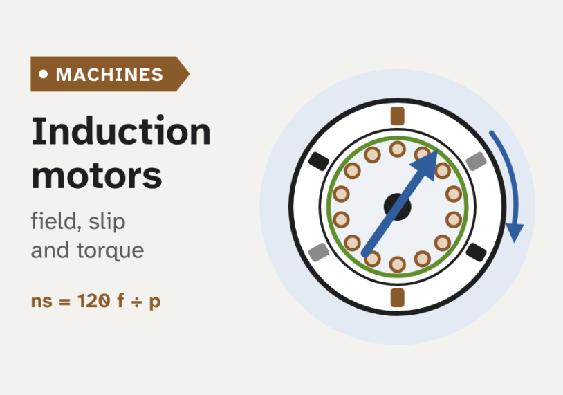
In this guide we see how an induction motor works, from the rotating field and slip to the torque–speed curve, starting and efficiency, with simple diagrams and a live demo.
Quick answer: An induction motor is an AC motor in which the stator’s rotating magnetic field induces current in the rotor, so the rotor needs no electrical connection. The field turns at synchronous speed, ns = 120f/p. The rotor always turns a little slower. This difference, called slip, is what induces the rotor current and makes torque. At full load the slip is usually 1–5%. Induction motors are simple, rugged and cheap, so they drive most of the world’s pumps, fans, compressors and conveyors.
What an induction motor is and why it is everywhere
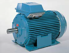
An induction motor is an AC electric motor. It turns electrical energy into mechanical energy, the turning of a shaft. It has two main parts. The stator is the fixed outer part. The rotor is the part that turns. A small air gap separates them.
In most motors, we must feed current into the rotor through brushes or a wired connection. The induction motor does not need this. The stator makes a magnetic field that turns. This field induces current in the rotor, the same way a transformer induces current in its secondary winding. That is where the name comes from.
So here is the question this article answers: how can a rotor with no wires connected to it be pushed around with real force?
The rotor never quite keeps up with the field. It always turns a little slower than the field when it works as a motor. So the induction motor is also called an asynchronous motor, a motor that does not run in step with the supply. A synchronous motor, in contrast, turns at exactly the speed of the field.
Induction motors are simple, strong and cheap to build. They need little maintenance, because a cage rotor has no brushes. Sizes range from a few watts in small fans to several megawatts in large pumps and compressors. Most three-phase motors in industry are induction motors.
Think of an induction motor as a transformer whose secondary winding can spin. The stator is the primary. The rotor is a short-circuited secondary. The rotating field carries energy across the air gap, and the rotor turns it into motion.
Inside the motor: stator and rotor
The figure below shows a cross-section of a three-phase induction motor and the two kinds of rotor.
The stator has three parts: the frame, the core and the winding.
- The frame is the outer housing. It holds the core and carries heat away, often with cooling fins.
- The stator core is a stack of thin steel sheets, called laminations. They are often about 0.5 mm thick and insulated from each other. This cuts the eddy currents, small circulating currents in the iron, and so reduces iron loss.
- The stator winding sits in slots on the inner edge of the core. It has three phases, spaced evenly around the stator. Small motors often use semi-closed slots, which lower the magnetising current but make the winding harder to insert. Large high-voltage motors use open slots, so pre-formed coils can be fitted.
The rotor also has a laminated core, fixed on the shaft. Its winding comes in two types.
Squirrel-cage rotor
A squirrel-cage rotor has a conducting bar in each slot. A ring at each end, the end ring, joins all the bars. Without the iron, the bars and rings look like a cage. Small and medium motors usually have aluminium bars cast into the rotor. Many large motors use copper bars brazed to copper end rings. The cage has no connection to the outside at all. This makes it very robust and cheap, so most induction motors use it.
Wound rotor
A wound rotor has a three-phase winding of insulated wire, like the stator. Its three ends go to three slip rings on the shaft. Carbon brushes press on the rings and connect the winding to an external resistor or a converter. Adding resistance raises the starting torque and lowers the starting current. It can also give some speed control. The cost is a more complex motor, brush wear and extra loss in the resistor. So wound rotors are used where the start is very heavy, such as large mills, crushers and cranes, or in wind turbines, as we see later.

How it works: the rotating field and slip
The rotating magnetic field
Each stator phase on its own makes a field that only pulses back and forth. But the three phase currents are 120° apart in time, and the three windings are 120° apart in space. Their three fields add up to one field of constant strength that turns smoothly around the air gap. This is the rotating magnetic field. The animation at the top of the page shows it.
The field turns at the synchronous speed, ns. It depends only on the supply frequency, f, and the number of magnetic poles, p, that the winding makes:
ns = 120 × f ÷ p (in rpm)
A 2-pole winding makes the field turn once per cycle. A 4-pole winding makes it turn once every two cycles, and so on. The supply frequency is 50 Hz in most of the world and 60 Hz in the Americas and some other countries. The table gives the common speeds.
| Poles (p) | ns at 50 Hz | ns at 60 Hz |
|---|---|---|
| 2 | 3000 rpm | 3600 rpm |
| 4 | 1500 rpm | 1800 rpm |
| 6 | 1000 rpm | 1200 rpm |
| 8 | 750 rpm | 900 rpm |
Mixing up poles and pole pairs. In ns = 120f/p, p is the number of poles. Some books use the number of pole pairs instead, and then the formula is ns = 60f/p. A 4-pole motor has 2 pole pairs. Using the wrong one doubles or halves the answer.
From field to torque
The four cards below follow how the rotating field turns into force on the rotor.
1Make a rotating field
The three stator currents are 120° apart in time. The three windings are 120° apart in space. Together they make one field that turns at synchronous speed.
2Induce a voltage in the bars
The field sweeps past the rotor bars. A moving field across a conductor induces a voltage, an EMF. The faster it sweeps past, the larger the EMF.
3Let current flow
The end rings short-circuit the bars. So the EMF drives a current around closed loops in the rotor. No wire from outside is needed.
4Get force and torque
A current in a magnetic field feels a force, F = B·I·L. The forces on all the bars push the rotor around, in the same direction as the field.
Slip: why the rotor must turn slower
Imagine that the rotor caught up with the field. Then the field would not move past the bars at all. No voltage would be induced, so no current would flow, and there would be no torque. Friction would slow the rotor down again. So in motor operation the rotor always turns a little slower than the field.
We measure this with the slip, s. It is the difference in speed, as a fraction of the synchronous speed:
s = (ns − n) ÷ ns
Here n is the rotor speed. We often give slip in percent, by multiplying by 100. At standstill s = 1. At synchronous speed s = 0. At full load, most motors run at about 1–5% slip, a little more for small motors and less for large ones.
The field slides past the rotor at the slip speed. So the rotor currents have a low frequency, the rotor frequency:
f2 = s × f
As the load grows, the rotor slows a little. The slip rises, so more voltage and current are induced, and the torque rises to match the load. The motor finds a new balance on its own. This is why an induction motor runs at an almost constant speed from no load to full load.
Think of a sailing boat running before the wind. The wind pushes the sail only while the boat is slower than the wind. If the boat reached wind speed, the sail would go slack. The rotating field is the wind, and the rotor is the boat. The bigger the load, the more the boat lags, and the harder the wind pushes.
The torque–speed curve
The torque–speed curve shows how much torque the motor makes at each speed. It is the most useful single picture of an induction motor. The figure below shows the curve for a typical 11 kW, 4-pole, 50 Hz motor. We worked it out from the motor's equivalent circuit, which we meet later.
Four points on the curve have names:
- Starting torque, or locked-rotor torque: the torque at standstill. Here it is about 2.2 times rated torque.
- Pull-up torque: the lowest torque while the motor speeds up from standstill to the breakdown point. In some motors the curve dips here. The load torque must stay below it, or the motor will hang at a low speed.
- Breakdown torque, also called pull-out torque: the peak of the curve. Here it is about 3 times rated torque. If the load is larger than this, the motor slows down and stalls.
- Rated torque: the torque at rated power and rated speed, 1460 rpm here. The motor runs on the steep part of the curve, between breakdown and synchronous speed.
On the steep right-hand part, the motor is stable. If the load rises, the speed falls a little, and the torque rises to meet it. Left of the breakdown point, it is the other way round: a slower speed gives less torque, so the motor slows further and stalls.
The effect of rotor resistance
More rotor resistance moves the peak to a lower speed. The size of the peak stays the same. So with the right resistance, the peak can appear at standstill, and the motor starts with its maximum torque. The dashed curve in the figure shows this. Wound-rotor motors use this idea with external resistors. But at normal speed, the extra resistance wastes power and makes the speed drop more with load. So the resistors are cut out once the motor is up to speed.
Cage motors use a trick to get both. At standstill, the rotor frequency is high, 50 Hz. The rotor current then crowds into the outer part of deep or double bars, where the resistance is high. At running speed, the rotor frequency is only 1–2 Hz, so the current spreads through the whole bar, and the resistance is low. This is the deep-bar or double-cage rotor.
NEMA and IEC designs
Manufacturers shape the curve for different loads. In North America, the NEMA MG 1 standard defines Designs A, B, C and D. The IEC 60034-12 standard defines similar designs: Design N is close to NEMA B, and Design H is close to NEMA C. The values below are typical. The exact limits depend on the motor size.
| NEMA design | Starting torque | Full-load slip | Typical loads |
|---|---|---|---|
| A | Normal, about 150–170% | Under 5% | Machine tools, fans |
| B | Normal, about 150% | Under 5% | Pumps, fans, compressors (most common) |
| C | High, about 200–250% | Under 5% | Loaded conveyors, crushers |
| D | Very high, 275% or more | 5–13% | Punch presses, hoists, flywheel loads |
Motor, generator and brake
The same machine can work in three ways, set by the slip.
- Motor, 0 < s ≤ 1. The rotor turns slower than the field, in the same direction. Electrical power goes in, and mechanical power comes out.
- Generator, s < 0. If a turbine or a falling load drives the rotor faster than the field, the slip is negative. The rotor current and the torque reverse. Now mechanical power goes in, and electrical power flows back to the supply. The machine still needs reactive power to magnetise it, from the grid or from a capacitor bank. Small hydro plants and older fixed-speed wind turbines use cage induction generators. Many modern wind turbines use a doubly-fed induction generator, a wound-rotor machine whose rotor is fed by a converter.
- Brake, s > 1. If the rotor turns against the field, the machine brakes hard. This happens when we swap two supply phases on a running motor, which is called plugging. The motor takes power from both the supply and the shaft, and all of it turns into heat in the rotor. So plugging is only used for short, quick stops, and the supply must be cut at zero speed.
Starting current and starting methods
At standstill, the slip is 1. The field cuts the rotor bars at full speed, so the induced rotor voltage is large. Only the small leakage reactance and resistance of the windings limit the current. So when we switch a motor straight onto the supply, it draws a large starting current, also called locked-rotor current. It is commonly about 6 to 8 times rated current, and the power factor is low. The current stays high until the motor is close to full speed.
This large current causes a voltage dip that other loads can feel, and it heats the motor. So larger motors often use a starting method that limits it. The figure below compares four methods on our 11 kW motor.
- Direct-on-line (DOL). A contactor connects the motor straight to the supply. It is the simplest and cheapest method, and it gives full starting torque. It suits small motors and strong supplies.
- Star-delta. The motor starts with its windings in star, so each winding gets 1/√3, about 58%, of its normal voltage. Line current and starting torque both fall to about one third of the DOL values. Near full speed, a timer switches the windings to delta. There is a short current peak at the switch-over. The method suits loads that start light, such as fans and centrifugal pumps.
- Soft starter. Thyristors, which are electronic switches, raise the voltage smoothly. The user sets a current limit, often 2 to 4 times rated current. Torque falls with the square of the voltage, so a soft starter suits light starting loads too.
- Variable frequency drive (VFD). A VFD changes both the frequency and the voltage. It starts the motor at a low frequency, so the slip is always small. The motor can make full torque from standstill with about rated current. A VFD also gives speed control for the rest of the time.
Autotransformer starters and, for wound-rotor motors, rotor resistance starters are also used. For more on drive setup, see our guide to 5 crucial VFD settings.
Using a star-delta starter on the wrong motor. Star-delta only works if the motor runs in delta on the local supply, and all six winding ends are brought out. For example, a 400 V Δ / 690 V Y motor suits a 400 V supply. A 230 V Δ / 400 V Y motor on a 400 V supply must run in star. Switching it to delta would put too much voltage on each winding.
Losses, efficiency and IE classes
We can study an induction motor with a per-phase equivalent circuit. It is the same idea as for a transformer: one phase of the motor, drawn as resistances and reactances. The rotor values are referred to the stator, which means they are scaled by the turns ratio, as we do for a transformer secondary.
The key part is the resistance R2(1 − s)/s. Its power is the mechanical power that the rotor develops. Its value depends on slip. At light load the slip is small, so this resistance is large and little current flows. As the load and slip grow, it falls, and the rotor current rises. At standstill it is zero, as if the rotor were short-circuited. This is why the starting current is so high.
The circuit also shows where the losses come from:
- Stator copper loss: I²R heating in the stator winding.
- Iron loss: hysteresis and eddy-current loss in the stator core. The laminations keep it low.
- Rotor copper loss: I²R heating in the rotor bars or winding.
- Friction and windage loss: bearing friction and the cooling fan.
- Stray load loss: small extra losses that grow with load, for example from harmonics in the air gap.
The power that crosses the air gap, the air-gap power, splits in a simple way:
rotor copper loss = s × air-gap power
The rest, (1 − s) times the air-gap power, becomes mechanical power. So a motor running at high slip wastes a large part of its power as heat in the rotor. This is why slip control with rotor resistance is inefficient.
Efficiency classes
The standard IEC 60034-30-1 sets efficiency classes for line-operated AC motors from 0.12 kW to 1000 kW. Each class has a minimum efficiency that depends on power, poles and frequency. The table shows the limits for an 11 kW, 4-pole, 50 Hz motor.
| Class | Name | Minimum efficiency* |
|---|---|---|
| IE1 | Standard | 87.6% |
| IE2 | High | 89.8% |
| IE3 | Premium | 91.4% |
| IE4 | Super premium | 93.3% |
*For an 11 kW, 4-pole, 50 Hz motor, from IEC 60034-30-1.
The 2025 edition of the standard adds an IE5 (ultra premium) class. Few induction motors reach IE5. Most IE5 motors today are synchronous reluctance or permanent-magnet motors. In the European Union, Regulation (EU) 2019/1781 has required IE3 for most three-phase motors from 0.75 kW to 1000 kW since 2021. Since July 2023 it requires IE4 for 2-, 4- and 6-pole motors from 75 kW to 200 kW.
Worked example: a 4-pole, 50 Hz motor
A motor nameplate gives its rated values. Rated power is the mechanical power at the shaft, in kW. Rated voltage and current are line values. Rated frequency is the supply frequency. Rated speed is the rotor speed at full load. The nameplate often also gives the power factor, the efficiency, the IE class, the insulation class and the duty type.
Our motor's nameplate says: 11 kW, 400 V, 50 Hz, 4 poles, 1460 rpm, efficiency 91.4% (IE3), power factor 0.82. Let us work out the main values.
- Synchronous speed. ns = 120 × 50 ÷ 4 = 1500 rpm.
- Slip. s = (1500 − 1460) ÷ 1500 = 40 ÷ 1500 ≈ 0.0267, or 2.7%.
- Rotor frequency. f2 = s × f = 0.0267 × 50 ≈ 1.33 Hz. So the rotor current changes direction slowly, about 1.3 times per second.
- Rated torque. First we turn the speed into angular speed: ω = 2π × 1460 ÷ 60 ≈ 152.9 rad/s. Then T = P ÷ ω = 11 000 ÷ 152.9 ≈ 71.9 N·m.
- Input power and current. Input power = 11 ÷ 0.914 ≈ 12.04 kW. Line current I = P ÷ (√3 × V × pf) = 12 040 ÷ (1.732 × 400 × 0.82) ≈ 21.2 A.
- Starting current. At about 6 to 8 times rated, a DOL start draws roughly 130 to 170 A for a few seconds. A star-delta start cuts this to about one third.
The figure below follows the power through the motor. The loss values are typical for this size of motor.
Check the rotor copper loss: s × air-gap power = 0.0267 × 11.42 ≈ 0.30 kW. So at rated load only about 2.7% of the air-gap power is lost in the rotor.
Now try it. The demo below uses the same motor. Move the load torque and watch the operating point slide along the torque–speed curve. At rated load, the motor runs at 1460 rpm. Doubling the load only drops the speed to about 1405 rpm. Above about 3 times rated, the load is larger than the breakdown torque, and the motor stalls.
Model: a typical 11 kW, 400 V, 50 Hz, 4-pole cage motor, worked out from its per-phase equivalent circuit. Friction and iron loss are left out. The motor runs where its torque equals the load torque, on the steep part of the curve.
Expecting the motor to run at the synchronous speed. A 4-pole, 50 Hz motor never runs at exactly 1500 rpm on load. The nameplate speed, here 1460 rpm, already includes the full-load slip. Also, the shaft speed falls a little as the load grows, so belt and gear ratios should use the real full-load speed.
Single-phase motors and where induction motors are used
Single-phase induction motors
Homes and small shops often have only a single-phase supply. A single-phase winding alone does not make a rotating field. Its field only pulses back and forth along one axis. We can think of this as two equal fields turning in opposite directions. At standstill their torques cancel, so the motor cannot start by itself. But once it turns, one field wins, and the motor keeps running.
So a single-phase motor has a second winding, the start winding, set 90° from the main winding. Its current must be shifted in time from the main current, so the two make a rotating field. There are several ways to do this:
- Split-phase: the start winding has more resistance than the main winding. This gives a small phase shift and modest starting torque.
- Capacitor-start: a capacitor in series with the start winding gives a larger shift and high starting torque. A centrifugal switch opens the start circuit at about 70–80% of speed. These suit compressors and pumps.
- Permanent split capacitor (PSC): a smaller capacitor stays in circuit all the time. Starting torque is low, but running is smooth and quiet. These suit fans and blowers.
- Capacitor-start, capacitor-run: one capacitor for starting and a smaller one for running. They give good starting torque and better running efficiency.
- Shaded-pole: a copper ring on part of each pole gives a weak rotating field. It is very cheap but inefficient, and is used in small fans.
Single-phase motors are less efficient than three-phase motors of the same size, and they make more noise and vibration. To reverse a split-phase or capacitor-start motor, we swap the start-winding connections, and the motor should be stopped first.
Where induction motors are used
- Pumps, fans and compressors: the largest group, in water supply, buildings and industry. Many now run on VFDs to save energy at part load.
- Conveyors, mixers and machine tools: constant-speed drives that need a strong start.
- Cranes, hoists and mills: once wound-rotor motors, now mostly cage motors on VFDs.
- Household appliances: refrigerator compressors, washing machines and fans, mostly single-phase.
- Traction: trains and some electric cars use three-phase induction motors fed by inverters. With a drive, they can run at speeds above 10 000 rpm.
- Generators: small hydro plants and wind turbines, as we saw above.
The main strengths are a simple and rugged build, low cost, little maintenance, and the ability to run straight from the supply. The main limits are a lagging power factor, meaning the motor draws reactive current to magnetise itself, which is worst at light load. The speed also falls a little with load, the starting current is high, and the efficiency is slightly lower than that of a permanent-magnet motor of the same size. A VFD removes most of these limits, but adds cost. To keep motors safe in service, see our guide to electric motor protection.
Key takeaways
- An induction motor works because the stator's rotating field induces current in the rotor. A cage rotor needs no electrical connection.
- The field turns at synchronous speed, ns = 120f/p, with p the number of poles. A 4-pole, 50 Hz field turns at 1500 rpm.
- The rotor must slip behind the field to induce current and make torque. Slip s = (ns − n)/ns is usually 1–5% at full load, and the rotor frequency is s × f.
- The torque–speed curve has a starting torque, a breakdown peak and a steep stable part near ns. More rotor resistance moves the peak to a lower speed but does not change its size.
- A direct-on-line start draws about 6–8 times rated current. Star-delta, soft starters and VFDs reduce it.
- Rotor copper loss equals s times the air-gap power. Efficiency classes IE1 to IE4 (and now IE5) are set by IEC 60034-30-1.
Next, we suggest comparing the induction motor with the synchronous machine, which runs exactly in step with the supply.
Related guides on Electrical Blog:
Synchronous vs asynchronous machines
Pingback: Electric Motor Protection - Types of Faults and Protection Devices Description - Electrical Blog